Series 200 Power Conditioners
Instruction Manual
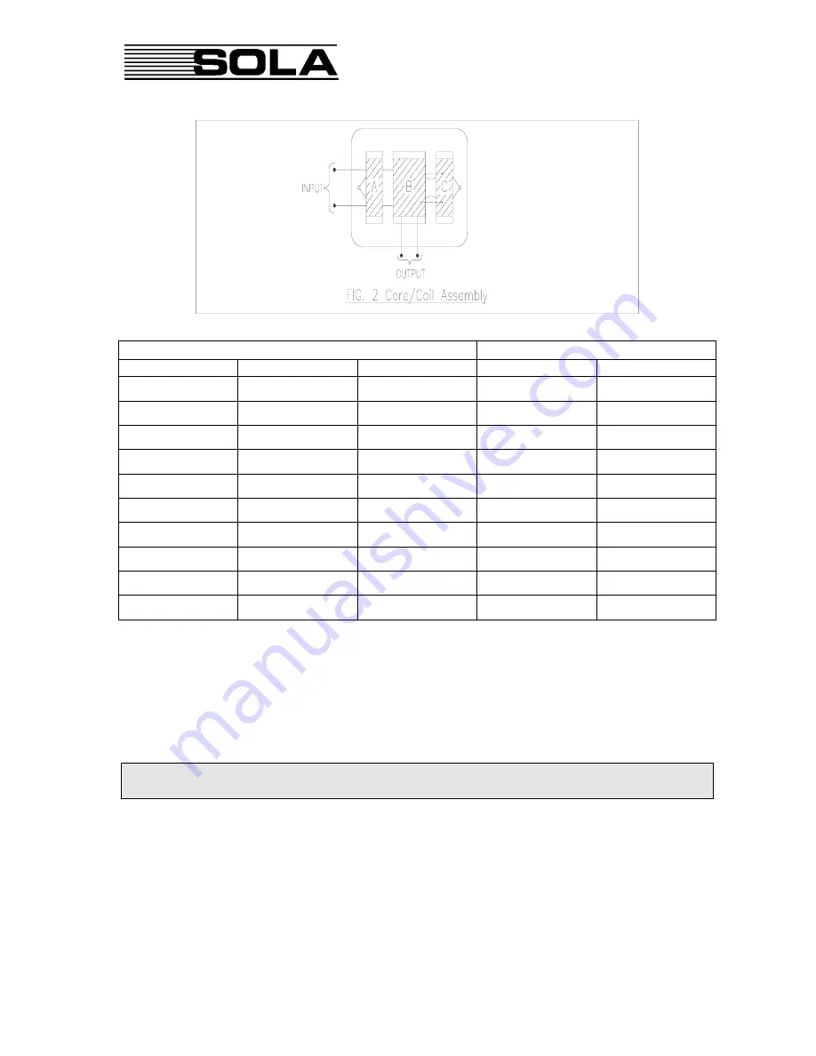
Part Number
Power
415 - 240V
400 - 230V
380 - 220V
kVA
Phase
200-26-730
200-25-730
20-44-730
3
1
200-26-730-00
200-25-730-00
N/A
3
1
200-26-750
200-25-750
200-44-750
5
1
200-26-750-HO
200-25-750-HO
N/A
5
1
200-26-775
200-25-775
200-44-775
7.5
1 or 3
200-26-790
200-25-790
200-44-790
9
1 or 3
200-26-812M
200-25-812M
200-44-812M
12
1 or 3
200-26-815
200-25-815
200-44-815
15
1 or 3
200-26-818
200-25-818
200-44-818
18
1 or 3
200-46-822
200-35-822
200-24-822
22.5
3
Table 1. Applicable Product Range
1.4
APPLICABLE PRODUCT RANGE
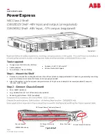
For power conditioners rated greater than 3kVA, 2 or more core/coil assemblies are connected
in parallel. Where 3 or 6 core/coil assemblies are used, a link system is provided to enable easy
site conversion to 3 Phase Y-Y configuration.
If 3 Phase configurations other than Y-Y are proposed,
you are advised to contact the factory before proceeding.
A typical connection diagram for 1 or 3 Phase (selectable) units is shown in Figure 3. All units
are shipped with an appropriate connection diagram mounted near the terminal panel.
All units are shipped with a 1 Phase configuration, except 22.5kVA with is 3 Phase only as
shown Figure 4.
- 2 -