- 41 -
- 41 -
6.10.2
TRACK MARKER DISC INCLINATION
ADJUSTMENT
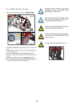
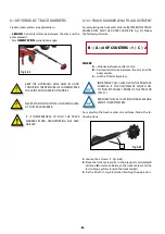
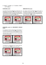
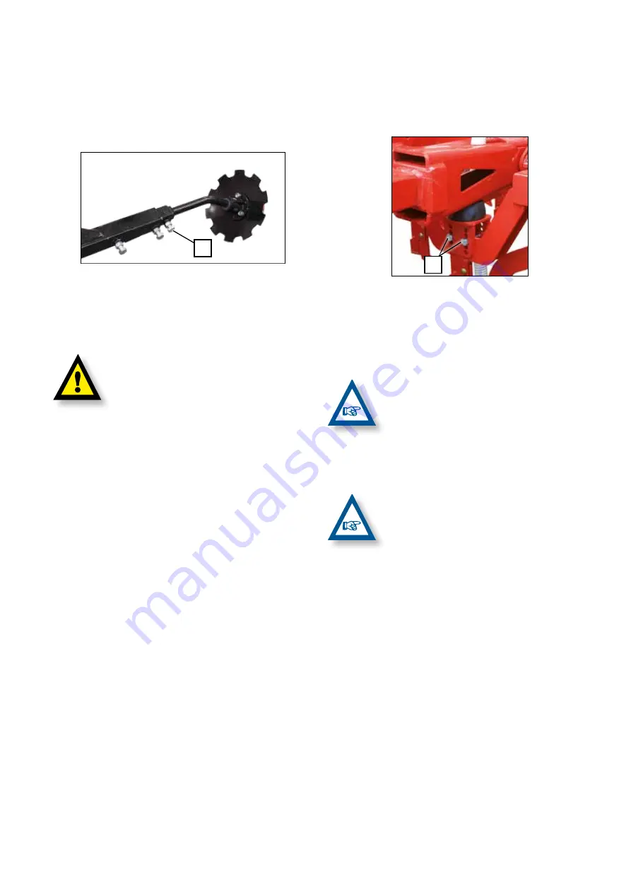
For adjusting the track marker disc inclination, follow the fo-
llowing steps:
Fig. 6.64
2
1-
Loosen the screw (2, Fig. 6.64).
2-
Regulate the track marker disc inclination for more or less
penetration into the ground.
3-
Tighten the screw (2, Fig. 6.64).
EXCESSIVE DISC ORIENTATION IS NOT ADVISA-
BLE SINCE IT CAN RESULT IN DAMAGE.
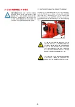
6.11 INCLINATION OF FOLDING PARTS
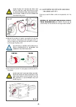
In the support point of the foldable part with the chassis,
two adjustable stops allow adjusting the drop angle.
Fig. 6.65
A
1-
Loosen the 2 fixing nuts (A, Fig. 6.65).
2-
Remove the 2 screws.
3-
Move the stop until the desired position.
4-
Introduce the 2 screws and fix them with the 2 nuts (A,
Fig. 6.65).
IN NORMAL SOWING CONDITIONS, IT IS ADVI-
SABLE TO LEAVE THE FOLDABLE PARTS SLIGHT-
LY DOWNWARDS IN ORDER TO GETTING ADAP-
TED TO THE TERRAIN IRREGULARITIES. FOR
BETTER ADAPTATION TO THE GROUND, LEA-
VE THE HYDRAULIC SYSTEM OF THE SOWING
EQUIPMENT IN NEUTRAL POSITION.
IN HIGHLY CULTIVATED GROUND OR, IN VERY
SOFT OR VERY WET SOIL THE FOLDABLE PARTS
SHALL BE LEVELLED UNTIL REACHING THE HO-
RIZONTAL POSITION.

