SOLA 4000 - Installation and Initial Start-Up
JUE 401265
30
1.5 CPNET Interface Card
The CPNET interface card is used for remote signalling of four
standard alarm conditions by means of voltage-free contacts in
programmable configurations.
1.5.1 Installation
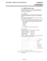
The CPNET interface card is a small pcb that is installed directly
underneath the CPU/NCP pcb, inside the front door of the UPS
cabinet.
It is connected to the UPS via the connector CN1 on the CPNET
pcb to CN10 on the CPU/NCP pcb.
It can be connected to remote devices via two different connectors:
• CN2, a 9 pin sub-D connector for standard computer connec-
tion. The following interface cables are available (see also
JUE 300 599):
- IBM AS-400
- Novell
- 3-COM
- Banyan Vines
• M1, a terminal block for individual configurations.
1.5.2 Functions
Contacts for the following alarm conditions are available:
Inverter Operation (N)
(CN1, pin 6)
Bypass Operation (B)
(CN1, pin 8)
Mains Failure (MF)
(CN1, pin 5)
Battery Low (BL)
(CN1, pin 7)
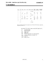
By means of the DIP switch SW1, the single relays and output pins
can be configured for each requirement.
SW1
INTERFACE
1
2
3
4
5
6
7
8
0
0
0
1
0
1
1
0
IBM-AS400
0
0
0
0
-
-
0
1
NOVEL
0
0
1
0
-
-
-
-
3-COM
0
0
0
0
-
-
-
-
BANYAN-VINES
0
1
1
0
-
-
0
1
BORRI VIKING
0
0
1
0
-
-
0
1
BORRI SIDEKICK
0
0
1
0
-
-
0
1
AMERICAN POWER
TAB. 1.5.2.1 Programming of the CP-NET pcb
Note:
Maximum rating of relay contacts: 250Vac, 6A (only when using
connector M1)
1 Installation


