SOLA 4000 - General System Description
JUE 401264
7
1 UPS Assembly
1.2 UPS System Structure
The basic SOLA 4000 power supply unit is an ac/dc/ac converter;
the block diagram: Figure 1.1 illustrates six essential functional
components:
• Rectifier/battery charger (6 pulse) (RECT.)
• Battery (BATT.)
• Inverter (INV.)
• Static inverter switch (SSI)
• Static bypass (SSB)
• Maintenance bypass (IBY)
All components are located in a single housing. They are explained
in detail on the following pages.The control electronics of the
rectifier, inverter and static bypass sections are completely inde-
pendent of each other. i.e. a failure in any one section will not
cause a failure in another section.
1.3 Rectifier/Battery Charger
In the standard configuration the charger is a three phase/6 pulse
rectifier that converts ac voltage to dc voltage. No isolation trans-
former is used and the rectifier is connected to the mains via the
commutation chokes which reduce the mains distortion created by
the rectifier. The dc output of the rectifier feeds the inverter and the
battery. The battery is connected to the rectifier through a satura-
tion choke which reduces ac ripple current to the battery, thus
ensuring the maximum battery life-time.
The rectifier is designed to feed both the inverter at maximum load
conditions and simultaneously the battery with maximum charging
current. Normally, the battery voltage is constantly regulated at 432
V dc (floating charge, maintenance-free lead battery, 2.25 volts per
cell). The rectifier's recharge characteristic is of the I/U type. This
means that the recharging current limitation is accomplished by
reduction of the dc voltage, thus assuring that the batteries will not
be damaged by excessive charging currents.
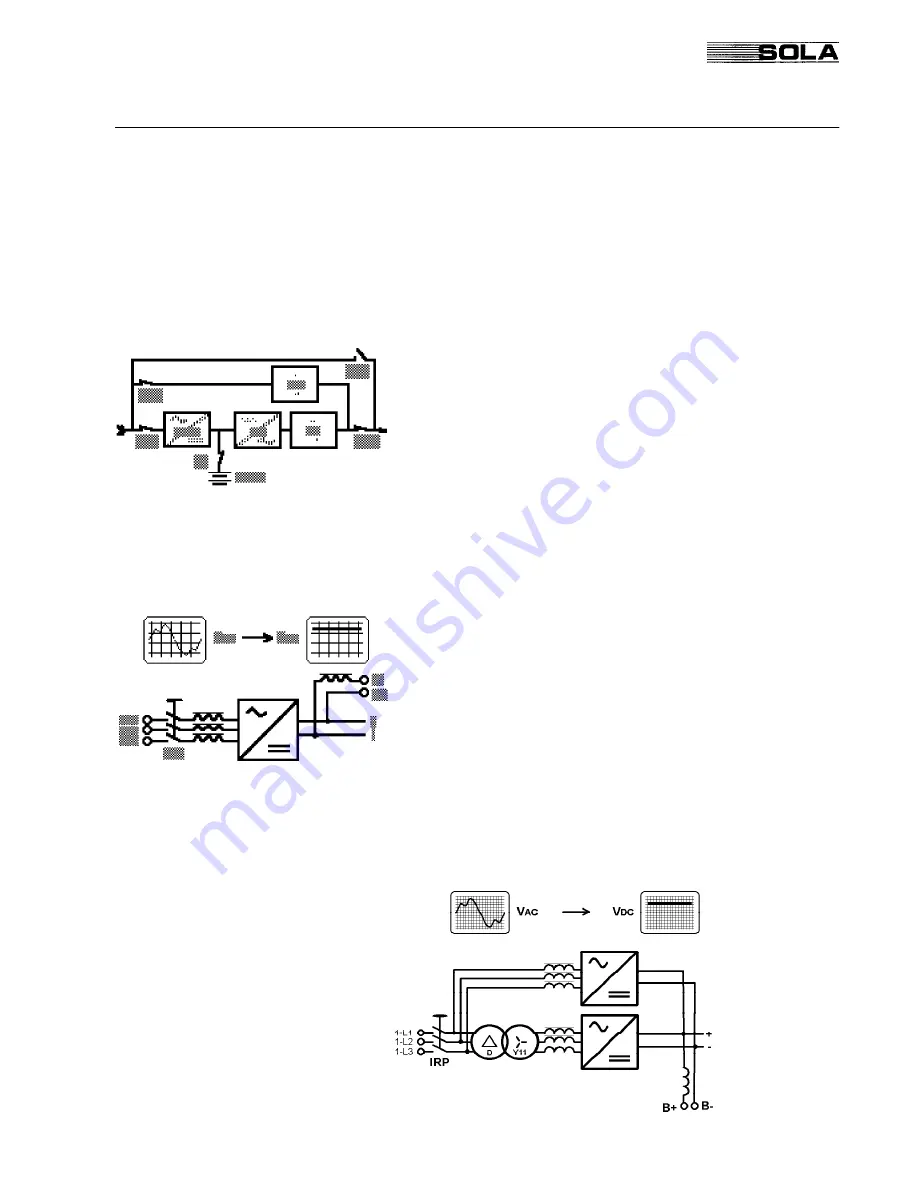
A 12-pulse rectifier is optional and requires the addition of a sec-
ond rectifier bridge inside the UPS cabinet and a phase shifting
transformer in a separate cabinet.
FIG. 1.3 - 12-pulse Rectifier Block-Diagram


