SOLA 4000 - Operation
JUE 401266
71
5 Operating Instructions
5.4 Switching Off / any one Unit within a Sys-
tem (Parallel and Hot-standby Systems)
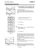
Initial UPS Operating Mode:
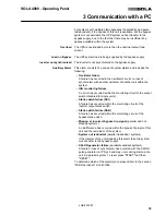
The UPS is in any operating mode described in the previous
sections "Operating Modes". All power switches except IBY are
closed, and the load is fed either through the inverter or the static
bypass.
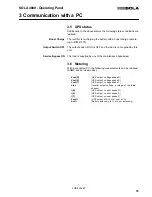
IPR:
S1
• At the bottom of the IPR pcb (if present), switch the
microswitch S1 to the manual position.
ICP:
PB2
• At the top of the ICP pcb, press the pushbutton PB2.
IRE:
• Open the
IRE
switch.
IUG:
• Open the
IUG
switch.
•
NOTE:
IN
ORDER
NOT
TO
AFFECT
SYSTEM
PERFORMANCE
, IUG
MUST
BE
OPENED
AT
THIS
MOMENT
.
IB:
• Open the battery switch
IB
.
IRP:
• Open the
IRP
switch.
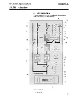
The rectifier voltage will slowly discharge and all the LED(s) on the
front panel will switch off. When all the LED(s) on all the internal
pcbs are off, the UPS module is free from voltage except at the
inputs of IRP, IRE and IBY and at the outputs of IUG and IBY and
at the respective terminals.
If this UPS module has an input supply separate to the other units
in the system, the input supply switch(es) to this module may now
be opened.
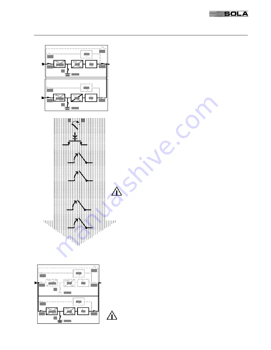
Final UPS Operating Mode:
The UPS module is now shut down. The load is supplied by the
remaining module(s) within the system.
Attention!
Even when the input supply to the UPS module is
isolated, there will still be voltage present at the output terminals
and the output of the switches IUG and IBY (from the remaining
modules within the UPS system).


