JUE 401267
90
SOLA 4000 - Operating Panel
5.3 Functions
General
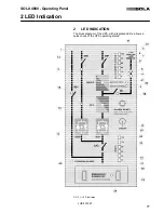
The Remote Panel provides the same LED indications as the
SOLA 4000 operating panel. Alarms are indicated by flashing LEDs
and an integrated buzzer. The alarms can be muted directly at the
Remote Panel by pressing the "Alarm Reset" push-button.
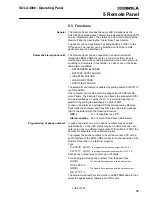
The buzzer can be deactivated by setting switch 2 of DIP1 to the
Off position. The inverter can be switched on from the remote
panel but cannot be switched off.
Automatic alarm phone calls
The Remote Panel can be connected to an external modem
through the RS232 DB9 connector, in order to perform an auto-
matic phone call to one or two programmed phone numbers (corre-
sponding to Computers in host Mode), in case of one of the below
listed alarm conditions:
• RETRANSFER BLOCKED
• BATTERY TEST FAILURE
• INVERTER FAILURE
• LOAD ON BYPASS
• RECTIFIER FAILURE
The automatic call feature is enabled by setting switch 3 of DIP1 to
the ON position.
One computer can receive alarm messages from 8 different Re-
mote Panels. The Remote Panels (and hence the connected UPS)
can be identified by a number from 1 to 8 which is binarily pro-
grammed by setting the switches 6,7 and 8 of DIP1.
In case of an alarm at a certain UPS the corresponding Remote
Panel calls the computer and transmits a two line alarm message
(ASCII characters) with the following structure:
UPS
x
x =1...8 identifies the UPS
Alarm condition
One or more of the above listed alarms
Programming of phone numbers
In case of an alarm one or two phone numbers may be called
automatically, i.e. the UPS status may be monitored by one com-
puter only or by two different computers. With switch 4 of DIP1 the
number of computers to be called can be set.
To program the phone numbers to be called connect a PC with a
serial interface to the RS232 DB9 connector on the rear side of the
Remote Panel and run a terminal program.
Type
P1XXXXX...X
[CR]
to program the first phone number (XXXXX...X)
P2YYYYY...Y
[CR]
to program the second phone number (YYYYY...Y)
Each phone number may contain up to 20 digits.
To read programmed phone numbers from the panel type
N1
[CR]
The Remote Panel responds with the first number:
N1=XXXXX...X
N2
[CR]
The Remote Panel responds with the second number:
N2=YYYYY...Y
The programmed numbers are stored in an EEPROM and are thus
protected against power failures and CPU resets.
5 Remote Panel

