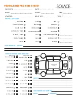
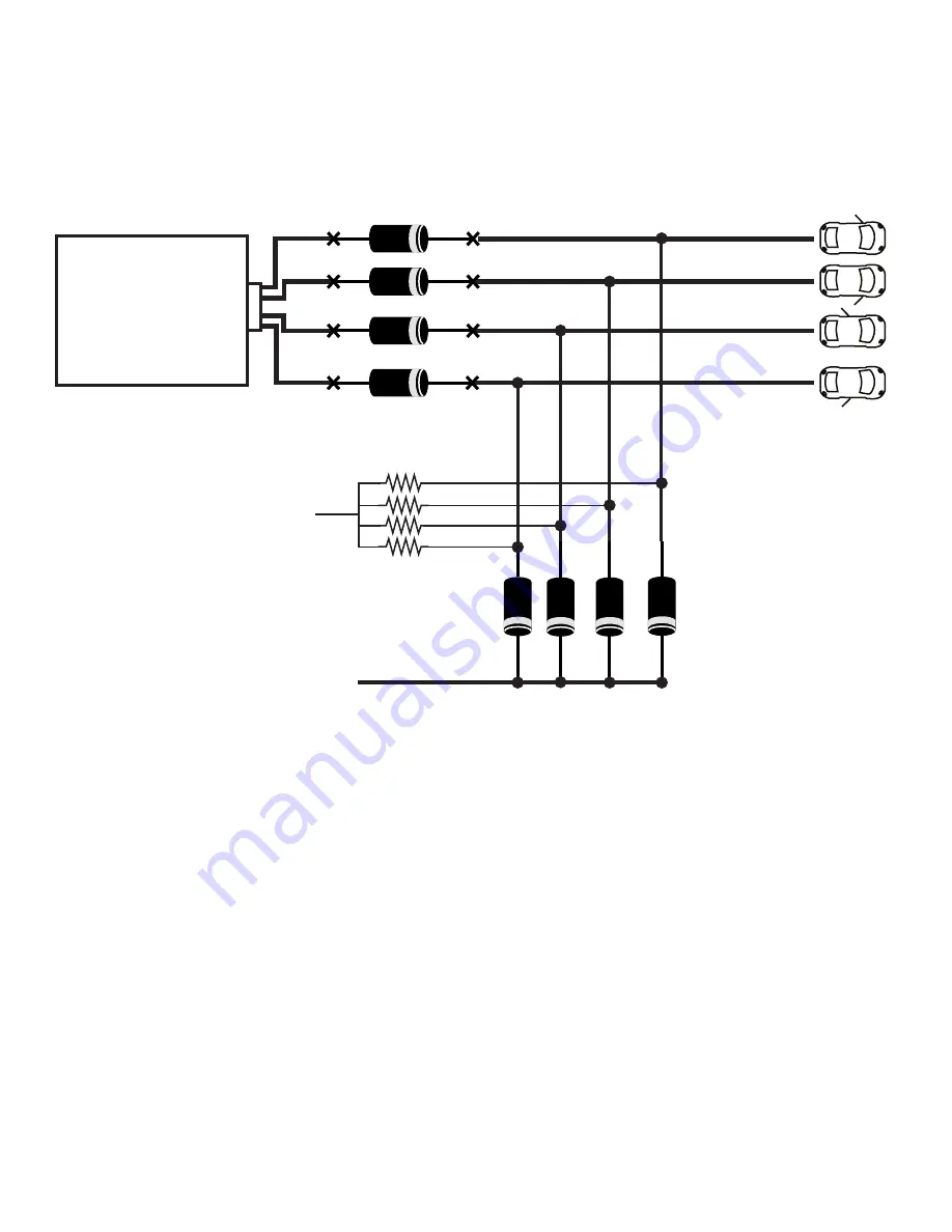
background image

MONITORING OPEN DOOR CIRCUIT FOR ALARM OR MANUAL TRANSMISSION (FORD, MAZDA)
(DIAGRAM COURTESY OF FORTIN ELECTRONICS)

DIODE DIAGRAMS 

CONTINUED

BCM

OR

SJB

FR DOOR PIN (OPEN)

FL DOOR PIN (OPEN)

RR DOOR PIN (OPEN)

RL DOOR PIN (OPEN)

3K RESISTORS

12 VOLTS +

POSITIVE DOOR PIN TO MODULE (+)

Summary of Contents for i Series

Page 1: ...AUTOMATIC MANUAL TRANSMISSION REMOTE STARTER EXTENDED INSTALL GUIDE iSeries Revision 4 02 08 2015 FW 51 ...

Page 2: ...N PINK 4 PARK BRAKE BLACK WHITE 5 DOOR IN GREEN 6 DOOR IN PURPLE 7 HORN BROWN BLACK 8 HOOD SWITCH IN GRAY 9 MULTIPLEX INPUT GRAY BLACK 10 AC TACHOMETER IN PURPLE WHITE 11 325mA GWA AUX WHITE PURPLE 12 325mA IGNITION AUX PINK BLACK 13 325mA ACCESSORY AUX ORANGE BLACK 14 325mA STARTER AUX PURPLE BLACK 15 325mA PARK LIGHT AUX WHITE BLACK 16 12V TO STARTER PURPLE 1 12V CONSTANT IN RED 2 12V TO 2nd IGN...

Page 3: ...INK WHITE SELECTABLE OUTPUT This wire is programmable in Menu 2 01 Whatever it is programmed for it will duplicate the output for a 2nd wire It is default set to Ignition Connect this wire to either 2nd Ignition 2nd Starter or 2nd Accessory Please be sure to program for the according wire on vehicle This wire can also be programmed to control a Positive trunk release PUSH TO START BRAKE output or ...

Page 4: ...Trunk PINK FOOT BRAKE STATUS INPUT This wire is the brake shutdown wire and MUST be connected to the vehicle s brake light wire when the foot brake is depressed This wire will disengage the remote starter when 12V is applied it also is used for the tach learning process NOTE Some newer vehicles must have the ignition on for the brake lights to be activated BLACK WHITE PARK BRAKE STATUS INPUT This ...

Page 5: ...e It is set to default as a Ignition output that will duplicate what the Pink Ignition wire on CN1 does NOTE this is a 325mA output and can be used with a relay to convert to a Positive output see relay guide This wire can be programmed to perform multiple other features Please see Menu 4 05 for a selection of outputs that can be programmed to ORANGE BLACK 325mA ACCESSORY OUTPUT This is a programm...

Page 6: ...t is can be used for auxiliary alarm sensors such as shock tilt audio and proximity PIN 4 GROUND OUTPUT This wire supplies a ground output is can be used for auxiliary alarm sensors such as shock tilt audio and proximity CN8 BYPASS SUPPLY WHITE PURPLE 325mA GROUND WHEN RUNNING This wire will send a output whenever the remote start is engaged This wire can be used in multiple scenarios the most com...

Page 7: ... switch 1 time and release The parking lights will flash and the siren horn will chirp once to confirm 3 Press and Hold valet button for 3 seconds The system confirms with 1 siren horn pulse and park light flash to confirm that it is now in Program Mode Selecting Program Menu 1 Once Program mode has been entered pressing the remote will select the different program menus as below Button 1 Lock wil...

Page 8: ......

Page 9: ......

Page 10: ... 87A 85 30 86 87 87A 85 30 86 GROUND GROUND 12 VOLTS 12 VOLTS UNLOCK RESISTANCE LOCK RESISTANCE BLUE UNLOCK GREEN LOCK POSITIVE ONE WIRE RESISTANCE TYPE DOOR LOCKS LOCK UNLOCK SWITCH 87 87A 85 30 86 87 87A 85 30 86 12 VOLTS 12 VOLTS UNLOCK RESISTANCE LOCK RESISTANCE DOOR LOCK RELAY DIAGRAMS ...

Page 11: ...K RELAY DIAGRAMS CONTINUED BLUE UNLOCK GREEN LOCK POSITIVE TYPE DOOR LOCKS LOCK UNLOCK SWITCH 87 87A 85 30 86 87 87A 85 30 86 12 VOLTS 12 VOLTS BLUE UNLOCK GREEN LOCK NEGATIVE TYPE DOOR LOCKS LOCK UNLOCK SWITCH ...

Page 12: ...PE DOOR LOCKS LOCK UNLOCK SWITCH 87 87A 85 30 86 87 87A 85 30 86 12 VOLTS 12 VOLTS BLUE UNLOCK GREEN LOCK ADDING AFTER MARKET DOOR LOCK ACTUATORS 87 87A 85 30 86 87 87A 85 30 86 12 VOLTS 12 VOLTS GROUND GROUND DOOR LOCK RELAY DIAGRAMS CONTINUED ...

Page 13: ...GAGED PIN 87A NORMALLY CLOSED CONTACT CONNECTED TO PIN 30 WHEN COIL IS NOT ENGAGED PIN 30 COMMON FEED SWITCHING A NEGATIVE START TO A POSITIVE START 87 87A 85 30 86 PURPLE BLACK START OUTPUT 12 VOLTS TO 2ND STARTER WIRE ON VEHICLE 87 87A 85 30 86 SWITCHING A NEGATIVE IGNITIION TO A POSITIVE IGNITION PINK BLACK IGNITIION OUTPUT 12 VOLTS TO 2ND IGNITION WIRE ON VEHICLE RELAY DIAGRAMS ...

Page 14: ... VOLTS TO 2ND ACCESSORY WIRE ON VEHICLE RELAY DIAGRAMS CONTINUED 87 87A 85 30 86 SWITCHING A NEGATIVE OUTPUT TO A POSITIVE OUTPUT NEGATIVE OUTPUT 12 VOLTS TO DESIRED POSITIVE OUTPUT 87 87A 85 30 86 SWITCHING A POSITIVE OUTPUT TO A NEGATIVE OUTPUT POSITIVE OUTPUT CHASSIS GROUND TO DESIRED NEGATIVE OUTPUT ...

Page 15: ... 87 87A 85 30 86 ISOLATING A WIRE 5 WIRE ALSO FOR MULTIPLEX SYSTEMS NEGATIVE SIGNAL FEED POSITIVE SIGNAL FEED TO CAR SIDE OF CUT WIRE 87 87A 85 30 86 CLOSING A WIRE CONNECTING 2 WIRES TO WIRE 1 TO BE CONNECTED TO WIRE 2 TO BE CONNECTED POSITIVE SIGNAL FEED TO SWITCH SIDE OF CUT WIRE POSITIVE SIGNAL FEED NEGATIVE SIGNAL FEED USED FOR MULTIPLEX SYSTEMS ...

Page 16: ...ED 87 87A 85 30 86 STARTER KILL ANTI GRIND ORANGE BLACK ACCESSORY OUTPUT 12 VOLTS TO CAR SIDE OF CUT STARTER WIRE TO SWITCH SIDE OF CUT STARTER WIRE KEY SWITCH START WIRE 87 87A 85 30 86 OPENING A WIRE CUTTING ALSO FORD OPEN DOOR R A P RADIO SHUTDOWN GREEN WHITE REARM OUTPUT 12 VOLTS TO CAR SIDE OF CUT DOOR PIN WIRE TO SWITCH SIDE OF CUT DOOR PIN WIRE DRIVERS DOOR PIN FOR FORD R A P SHUTDOWN ...

Page 17: ...LOWS THIS WAY SWITCHING 1 NEGATIVE WIRE TO 2 NEGATIVE ISOLATED WIRES NEGATIVE FEED ISOLATED NEGATIVE WIRE 1 ISOLATED NEGATIVE WIRE 2 SWITCHING 1 POSITIVE WIRE TO 2 POSITIVE ISOLATED WIRES POSITIVE FEED ISOLATED POSITIVE WIRE 1 ISOLATED POSITIVE WIRE 2 ...

Page 18: ...S DIODE DIAGRAMS CONTINUED RL DOOR PIN FR DOOR PIN NEGATIVE DOOR PIN TO MODULE ISOLATING A NEGATIVE FALSING DOOR PIN WIRE FOR ALARM BCM NEGATIVE DOOR PIN TO NEGATIVE DOOR INPUT ON ALARM ISOLATING A POSITIVE FALSING DOOR PIN WIRE FOR ALARM BCM POSITIVE DOOR PIN TO POSITIVE DOOR INPUT ON ALARM FL DOOR PIN RR DOOR PIN RL DOOR PIN FR DOOR PIN ...

Page 19: ... ALARM OR MANUAL TRANSMISSION FORD MAZDA DIAGRAM COURTESY OF FORTIN ELECTRONICS DIODE DIAGRAMS CONTINUED BCM OR SJB FR DOOR PIN OPEN FL DOOR PIN OPEN RR DOOR PIN OPEN RL DOOR PIN OPEN 3K RESISTORS 12 VOLTS POSITIVE DOOR PIN TO MODULE ...

Page 20: ...Red White wire from CN1 to the other STARTER This wire provides a 12V Source to the starter directly or to the starter circuit on the vehicle To test for this wire use a multi meter set to DC Voltage with one lead to chassis ground and the other lead to probe for a wire that reads between 10 16Volts when the key is in the Start Crank position in the key switch Connect the Purple wire on CN1 to thi...

Page 21: ... Voltage with one lead to 12V Constant and the other lead to probe for a wire that reads between 10 16Volts when just the park lights are turned on by the switch Connect the White Black wire on CN4 to this wire to It may be possible that a negative park light wire be Multiplexed In this case please refer to the Relay Diagram for installation HORN This wire will be usually found at the clock spring...

Page 22: ...and connect the wire accordingly TACHOMETER OR RPM AC There are multiple locations to get a tach signal Most common is either at an ignition coil or fuel injector Other locations include camshaft or crank position sensor and the instrument cluster At either a coil or an injector there most likely will be an uncommon wire color across all of them To test this wire START THE VEHICLE and use a multi ...

Page 23: ... DOOR PIN This wire can usually always be found at the door pin switch and can usually be found at the BCM or at the instrument cluster To test for this wire use a multi meter set to DC Voltage with one lead to 12V Constant and the other lead to probe for the door pin wire If the wire reads between 10 16Volts when the door is open then the door pin is negative and you can connect the Green wire on...

Page 24: ... becoming more popular that locks can be controlled using a bypass module To test for this wire use a multi meter set to DC Voltage with one lead to 12V Constant and the other lead to probe for a wire that reads between 10 16Volts when the lock button is pressed Connect the Green wire on CN2 to this wire There are multiple changes that can be made to the way this wire functions in Menu 1 01 to 1 0...

Page 25: ...3 AUX 4 DEFROST HEATED SEATS TRUNK PIN AUX ALARM SENSORS BYPASS INVOICE ______________________ _______________ AC200 200 GPS _______________ _______________ OTHER INSTALL NOTES VEHICLE NOTES AND DAMAGE NOTES DATE INSTALLER CHECK IN OUT CHECK IN OUT PWR WINDOWS PWR LOCKS WIPERS PWR TRUNK PARK LIGHTS HEADLIGHTS TURN SIGNALS BRAKE LIGHTS HAZARD LIGHTS DASH LIGHTS DOMELIGHT PWR HEAT SEATS HORN REAR DE...

Page 26: ......

Page 27: ......

Page 28: ...Solace Technologies Limited 17302 116 Ave Edmonton AB T5S 2X2 p 780 443 4379 tf 1 855 SOLACE5 f 780 443 4137 tff 1 855 SOLACE6 www SolaceRemoteStarters com ...

Reviews: