TESTING VEHICLE WIRES
CONTINUED
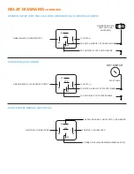
WHEN LOOKING FOR A POSITIVE (+) WIRE CONNECT ONE LEAD OF YOUR MULTI METER TO A CHASSIS
GROUND.
WHEN LOOKING FOR A NEGATIVE (-) WIRE CONNECT ONE LEAD OF YOUR MULTI METER TO A 12V (+)
CONSTANT SOURCE
DISARM (-)
- Refer to Step 3 of Testing for Alarm.
If it disarms by the key in the door cylinder then find the wire that duplicates this.
To test for this wire use a multi meter set to DC Voltage with one lead to 12V(+) Constant and the other lead
to probe for a wire that reads between 10-16Volts (-) when the key is turned to the unlock position in the door
cylinder. Connect the Blue/White wire on CN3 to this wire.
In the case the vehicle needs to be started to disarm the alarm please program special disarm options in Menu
1-06 to option 2. Whenever unlock is pressed the remote starter will automatically simulate turning the ignition
on for 1 second, in turn disarming the OEM Alarm system. No extra wire connections are required for this type.
It is also possible that the OEM Alarm can only be disarmed by the factory OEM Keyless remote. In this case
please check for bypass module compatibility.
REARM (-)
- Refer to Step 1 of Testing for Alarm.
If it rearms by the key in the door cylinder then find the wire that duplicates this.
To test for this wire use a multi meter set to DC Voltage with one lead to 12V(+) Constant and the other lead to
probe for a wire that reads between 10-16Volts (-) when the key is turned to the lock position in the door cylinder.
Connect the Green/White wire on CN3 to this wire.
In the case the vehicle needs have the door open while pressing lock on the door panel switch please refer to
finding a door pin wire in this part of the guide and connect the wire accordingly.
TACHOMETER OR RPM (AC)
- There are multiple locations to get a tach signal. Most common is either at an
ignition coil or fuel injector. Other locations include camshaft or crank position sensor, and the instrument
cluster, At either a coil or an injector there most likely will be an uncommon wire color across all of them.
To test this wire START THE VEHICLE and use a multi meter set to AC Voltage with one lead to chassis ground
and the other lead to probe for a wire that will read between 1-6Volts and will normally change with increase and
decrease of engine RPM. Connect the Purple/White wire on CN3 to this wire.
Solace remote starters also have the capability of running in tachless mode where there is no connection
required to monitor if the vehicle is running or not. Please refer to the Tach Learning procedure for more
information.
BRAKE SWITCH (-)
- This wire can usually always be found at the brake switch but on most vehicles can be
found at the fuse box or Driver’s Kick Panel.
To test for this wire use a multi meter set to DC Voltage with one lead to chassis ground and the other lead to
probe for a wire that reads between 10-16Volts (+) when the foot brake is depressed and neutral or negative
when the brake is not depressed. Connect the Pink wire on CN3 to this wire.
PARK BRAKE(-)
- This wire can usually always be found at the emergency brake switch or at the instrument
cluster. On some vehicles it can also be found at the Daytime Running Light module behind the dash.
To test for this wire use a multi meter set to DC Voltage with one lead to 12V(+) Constant and the other lead to
probe for a wire that reads between 10-16Volts (-) when the park brake is engaged and neutral or negative when
the park brake is not engaged. *NOTE some vehicles may have to be running to test this wire properly. Connect
the Black/White wire on CN3 to this wire.

