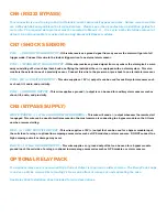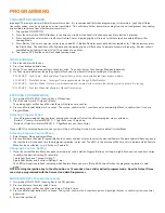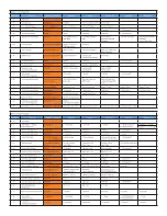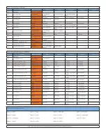
GRAY/BLACK - (+/-) WAIT TO START/MULTIPLEX INPUT
-
This wire is used to detect the Glo Plug light on diesel
engines. With this wire connected, the crank will be delayed until the glow plug light goes out. This wire will monitor either
a (+) or (-) glow plug light and wait up to 30 seconds before cranking. If you wish to set a specific timed delay do not connect
this wire and program the desired time in Menu 2-04. When used a multiplex input his wire is a multipurpose resistance input
wire that has the capabilities to allow multiple inputs from trunk status to disarm in. Please follow the multiplex chart for
more info, must be programmed in Menu 2-05
PURPLE/WHITE - (AC) TACHOMETER/RPM INPUT
-
This wire is the
tachometer or RPM signal input. Connect this
wire to a valid tach source, i.e. coil pack or injector. This wire is monitored by the remote starter and disengages the crank
output once the vehicle is running. Once this wire is connected you must perform a “tach learn” by starting the vehicle by key
and holding the brake while pressing the program button once. If you wish to use a tachless setting or tach through data link
DO NOT connect this wire and perform a “tach learn” and the module will automatically detect which tach setting is best for
the vehicle. You can also program this setting in Menu 2-13.
WHITE/PURPLE - (-) 325mA GROUND WHEN ARMED OUTPUT
-
This is a programmable output wire. It is set to
default as a Ground When Armed, meaning when the remote starter is in a locked state this wire will have a ground output.
When the remote starter is in the unlocked state this wire will be in a neutral state. This wire can be programmed to perform
multiple other features. Please see Menu 4-04 for a selection of outputs that can be programmed to.
PINK/BLACK - (-) 325mA IGNITION OUTPUT
-
This is a programmable output wire. It is set to default as a (-)Ignition
output that will duplicate what the Pink (+) Ignition wire on CN1 does. NOTE this is a 325mA (-) output and can be used with
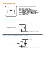
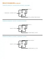
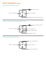
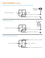
a relay to convert to a (+) Positive output (see relay guide). This wire can be programmed to perform multiple other features.
Please see Menu 4-05 for a selection of outputs that can be programmed to.
ORANGE/BLACK - (-) 325mA ACCESSORY OUTPUT
-
This is a programmable output wire. It is set to default as a
(-) Accessory output that will duplicate what the Orange (+) Accessory wire on CN1 does. NOTE this is a 325mA (-) output
and can be used with a relay to convert to a (+) Positive output (see relay guide). This wire can be programmed to perform
multiple other features. Please see Menu 4-06 for a selection of outputs that can be programmed to.
PURPLE/BLACK - (-) 325mA STARTER OUTPUT
-
This is a programmable output wire. It is set to default as a (-)
Starter output that will duplicate what the Purple (+) Starter wire on CN1 does. NOTE this is a 325mA (-) output and can be
used with a relay to convert to a (+) Positive output (see relay guide). This wire can be programmed to perform multiple other
features. Please see Menu 4-07 for a selection of outputs that can be programmed to.
WHITE/BLACK - (-) 325mA PARK LIGHT OUTPUT
-
This is a programmable output wire. NOTE this is a 325mA (-)
output and can be used with a relay to convert to a (+) Positive output (see relay guide). This wire can be programmed to
perform multiple other features. Please see Menu 4-08 for a selection of outputs that can be programmed to.
BROWN/BLACK - (-) 325mA HORN OUTPUT
-
This wire is sends out a 325mA output to control the vehicles horn.
Connect this wire to the (-) Horn wire on the vehicle. This wire can also be used as (-) Siren wire. This wire is programmable
for multiple features and it’s timing can be changed in Menu 3-06, 3-07, and 3-08.
CN5 (ANTENNA)
This connector is used for the antenna, Solace PC Cable (SPCC) for firmware updates, and also the Solace
Handheld Programmer (SHHP) which can be used to program all features of this remote starter.


