WATTrouter ECO - user manual
www.solarcontrols.cz
How to fit and setup the device
Page 14 from 66
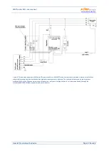
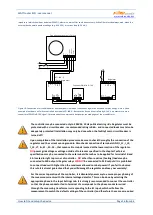
Figure 6: Three-phase connection of WATTrouter ECO with 2 regulators and without low tariff signal circuit (CombiWATT mode cannot
be used). Using this connection you may extend the number of outputs up to 12. Current sensing module is placed at the facility’s supply
cable coming from the distribution box where main energy meter is located. Connected loads use only the actual surpluses produced by
PV-plant. To make things simple, only 3 resistive (heating) loads are connected, but you may use all 12 outputs. Similarly, you may also
connect 3 regulators to 1 current sensing module. In such scenario, each regulator works on one phase and you will get 18 outputs.
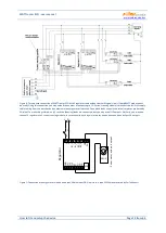
Figure 7: Connection of energy meter with pulse output S0 with input FB. On picture is type EM10 manufactured by Carlo Gavazzi.
L N
I >
Re
gul
at
or
I_
L1
I_
L2
I_
L3
G
ND
S2-
S+ S1-
R2
_1
R2
_2
L
N
LT
R1
_1
R1
_2
USB
FB S4-
S3-
EM10
Po
w
er
m
et
er
w
it
h
pu
ls
o
u
tpu
t


