WATTrouter ECO - user manual
www.solarcontrols.cz
How to fit and setup the device
Page 15 from 66
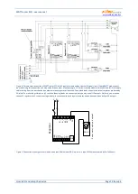
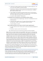
Figure 8: Increasing of current measurement range of the device for facilities where main circuit breaker is larger than 3x40A.
Transformers 200/5A, or even 400/5A may be used, based on the main circuit breaker value. Secondary coil of current transformers is
shorted through the current sensing module (the secondary circuit passes through measuring transformers in the current sensing
module). Additional increase of current measurement range may be done if you take the secondary circuit of the current transformer
and make several turns through the measuring transformer in the current sensing module (for transformers 200/5A, the best option is
to make 4 turns in order to reach optimum transfer ratio 200/20A). For this purpose we recommend using lines, which are not overrated
for the nominal secondary current, just to be able to make more turns through the hole of measuring transformer. When WATTrouter
connected through external current transformers, the conversion ratio must be set correctly in the control software - see the item
Conversion ratio of external CT‘s in the main window of the WATTconfig ECO software.
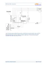
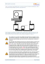
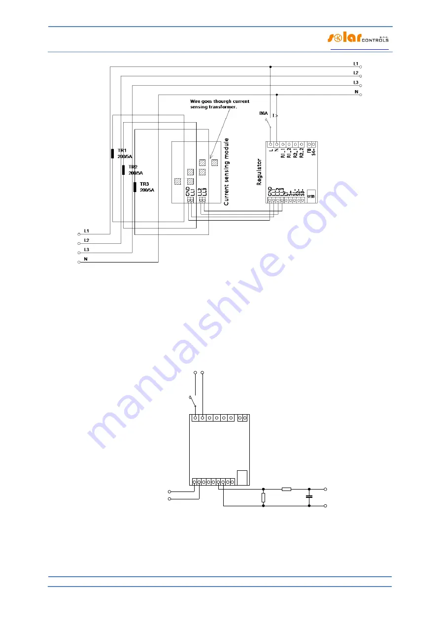
Figure 4: Connection of external devices controlled with a voltage of 0-5 VDC. The SSR output has to be operated in PWM mode. PWM
signal is presented on terminal S1-(for output S2 on terminal S2- etc.). The filter element (R2 and C1) produces DC voltage with typical
residual ripple about 300 mV. If you need inverted signal then connect the filter element between the S1- and GND terminals. The
resistor R1 must always be connected between the S+ and Sx- terminals because the Sx- terminals have only open collector drive with a
very weak internal pull-up resistor. The connected device must have a corresponding control input with sufficiently high input
L N
I >
Re
gul
at
or
R1
10K
R2
47K
C1
330n
+
-
0-5 VDC
to measuring module
I_
L1
I_
L2
I_
L3
G
ND
S2-
S+ S1-
R2
_1
R2
_2
L
N
LT
R1
_1
R1
_2
USB
FB S4-
S3
-


