WATTrouter ECO - user manual
www.solarcontrols.cz
How to fit and setup the device
Page 16 from 66
impedance (which should not be below 200 kΩ); otherwise active filter could be necessary. Active filter must be always used, when the
external device awaits another voltage (e.g. 0-10 VDC) or current loop (4-20 mA).
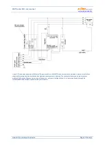
Figure 10: Connection of air conditioner or heat pump unit in mode of continuous regulation based on surplus energy. Here is listed
example of outdoor unit Fujitsu controlled by module UTI-INV-G. Because this device is controlled by 0-10V, it is necessary to use a
converter of PWM to 0-10V signal. For more about connection of heat pumps, see web pages of the manufacturer.
The controller may be connected only to 230VAC, 50 Hz public electric grids. Regulator must be
protected with a circuit breaker - recommended rating is B6A - and connected loads must also be
adequately protected! Installation may only be done when the facility’s main circuit breaker is
turned off!
Upon completion of the installation process make sure to check thoroughly the connection of the
regulator and the current sensing module. Also check connection of terminals GND, I_L1, I_L2,
I_L3, LT, S+, S1-, S2-, S3-, that means all terminals located at the lower section of the regulator.
NO
power grid voltage or voltage outside of tolerances specified in the chapter Technical
specifications may be connected to these terminals! Same has to be applied for terminals FB and
S4- located in right top corner of controller.
NO
other than resistive (heating) loads may be
connected to SSR outputs! Regular relays
CANNOT
be connected to SSR outputs! It is prohibited
to connect loads with higher than the maximum allowed nominal power! If you fail to observe
this rule it is almost guaranteed that you will damage the regulator and lose your warranty!
For the correct operation of the controller, it is absolutely necessary to ensure proper phasing of
the measured currents with the internal voltage detector. This can be done by selecting the
appropriate phase in the Input Settings tab. It is strongly recommended to connect the controller
so that the phase conductor fed to terminal L1 corresponds to the phase conductor wired
through the measuring transformer corresponding to the IL1 input, which will allow the
measurement to match the default settings of the controller (and therefore the same as required
L N
I >
Convertor PWM to 0-10 V
+
12
V
G
ND
0-
10V
G
ND
+
PWM
-PWM
ON H
/C
+
12
V
G
ND
TH
G
ND
N
C
L
ON
ER
R
D
EF
ON2
UTI-INV-G
(Corp. Impromat)
One phase outdoor unit Fujitsu
PE
L
N
1
(bl
ac
k)
2
(w
hi
te)
3
(re
d)
I >
PE
L
N
Regulator
I_
L1
I_
L2
I_
L3
G
ND
S2
-
S+ S1-
R2
_1
R2
_2
L
N
LT
R1
_1
R1
_2
USB
FB S4
-
S3-


