WATTrouter ECO - user manual
www.solarcontrols.cz
How to fit and setup the device
Page 25 from 66
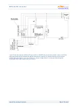
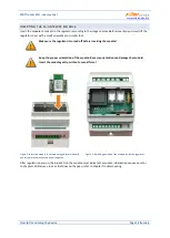
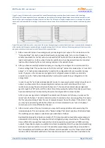
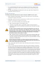
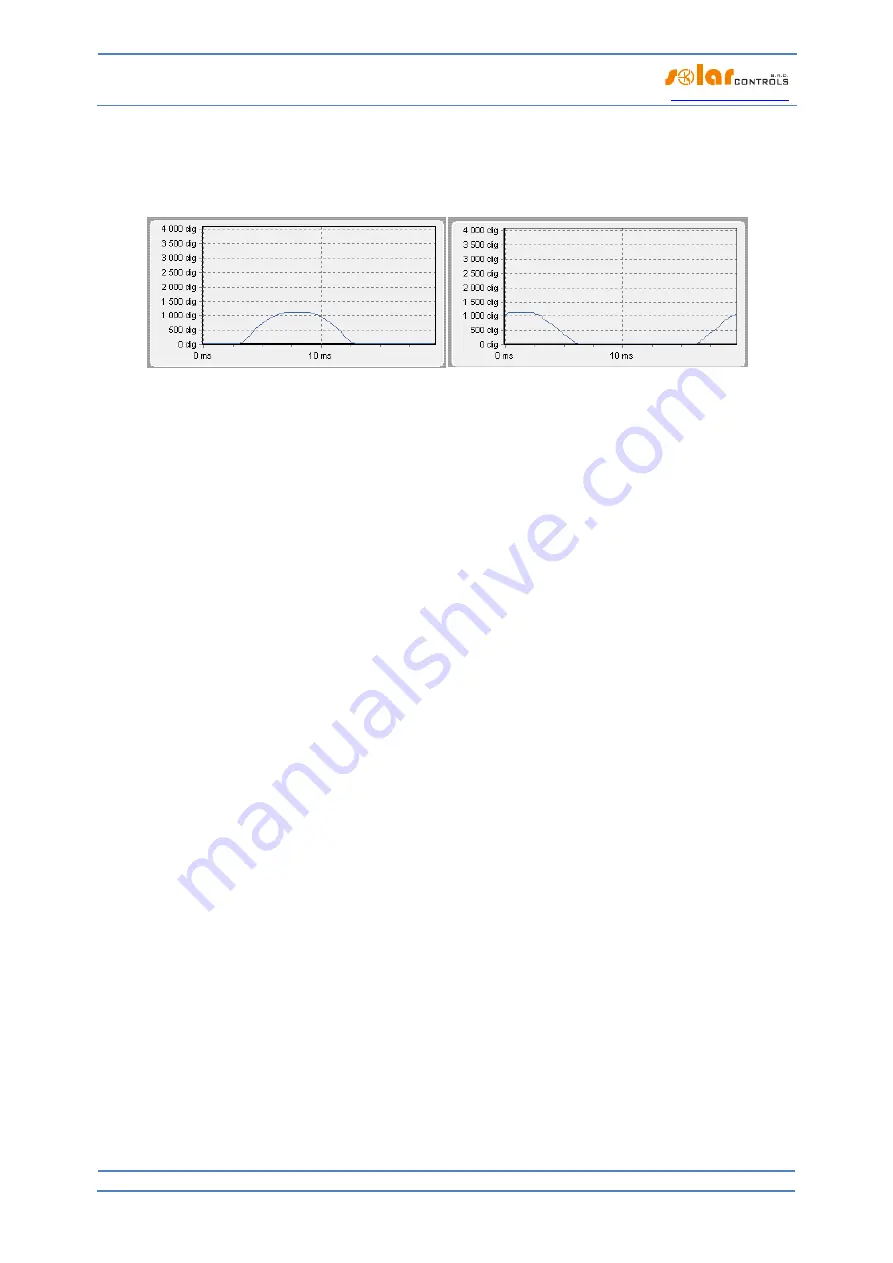
Figure71: Input is fitted correctly - sine wave of the current flowing through a resistive (heat) load is in phase with the voltage.
WATTconfig ECO shows negative values on selected phase (consumption). Left image appears when there is normal (default) current
flow direction, right image appears for opposite direction. Note: The PV-inverter throughput appears exactly as the opposite, because
the current is anti-phased with the voltage. If the inverter performs power factor compensation you can observe corresponding phase
shifts.
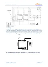
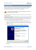
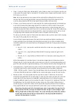
Figure 82: Input is fitted incorrectly - sine wave of the current flowing through a resistive (heat) load is not in phase with the voltage and
either precedes (left image) or lags behind (right image) the voltage by 1/3 of mains half-wave. Measuring inputs are fitted incorrectly
and you need to select correct option in the Phase field for respective input.
7.
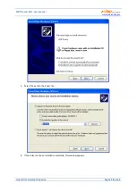
After a successful setup of measuring inputs you may begin to test outputs. This can be done on the
"Output settings" tab. Each connected load must be tested separately. Turn on circuit breaker or
activate fuse switch for the first output, and press the TEST button for the corresponding output. The
load should switch on. Further, when the load is switched on, the active power drawn by connected
load must be detected by the current sensing module on the relevant phase.
8.
After you have successfully tested all outputs, you may begin to configure the control mode in the
Control settings field. This can be done on the "Other settings" tab. Set this mode either to "sum of all
phases" or to "each phase independently", based on the configuration of your 4-quadrant energy
meter. If you are not sure how your energy meter is configured, please contact your electricity
provider or use the "each phase independently"-mode, which works for any configuration of the
energy meter.
In order to use the "each phase independently"-mode, it is necessary to select correct phase for each
output, i.e. phase where the corresponding load is really connected. Controller will then try to
maintain zero energy flow in each phase ("phase zero"). You may check correct phase assignment
again through the TEST button. Within a short time after pressing the button the active power drawn
by connected load must be detected by the current sensing module on relevant phase.
As far as your energy meter is configured to evaluate sum of powers in all phases, you may use the
mode "sum of all phases". Here the controller will try to maintain virtual zero energy flow. This means
that for output switching it takes the sum of measured powers from all 3 phases ("virtual zero"). Here
you may try experimenting with both methods, but it is recommended to use "sum of all phases"-
mode, because it is more effective for the user.
9.
After a correct setup of the control mode, you may start to assign priorities and power ratings for
individual outputs. This can be done on the "Output settings" tab. Select priorities of individual loads.
The switching process based on priorities may be described as follows:
By default (during night), all loads are turned off. If PV-plant production (available surplus energy) is
determined in the morning, the output with the first (highest) priority is switched on. The switching
time is different for proportional outputs (their function equals to proportional or PWM) and relay
outputs. Proportional outputs are switched on almost immediately (this is the proportional switching),
but relay outputs are switched on only if the available surplus energy exceeds the value specified in
the Connected power field (there is also a different solution available – see the "Prepend before SSRs"
function). When the load is switched on (for proportional output it means the load is switched to the


