background image

WATTrouter ECO - user manual 


www.solarcontrols.cz


How to fit and setup the device 

Page 27 from 66 


b.


PV-plant does not produce electric power (active powers at all measured phases are <= (less 
than or equal to the) CombiWATT production limit field). 

c.


During the day, PV-plant did not supply the load with the required amount of energy, that is, 
the field "Assumed supplied energy" is lower than the value specified in the "CombiWATT 
[kWh]" field for the relevant output. 

d.


Low tariff signal has been detected (the information field "low tariff" is red). Energy from 
public grid is always consumed in CombiWATT only if low tariff is 

present

. See note below to 

learn how to configure this mode if you don't have double tariff rate. 

e.


The "Time to activate CombiWATT"-field shows zero. 

The CombiWATT mode is deactivated if some of the following conditions will apply: 

a.


The value in the field "Assumed supplied energy" reached the "CombiWATT [kWh]" value for 
the relevant output. 

b.


Production has been detected at some of the measured phases (active power at some 
measured phase is > (greater than the) CombiWATT production limit field). 

c.


The low tariff signal is turned off. 

Reset of energy counters (that is reset of values in the fields "Assumed supplied energy") 

a.


At sunrise. Counters are reset to zero at sunrise time, which is automatically calculated by the 
controller. 

b.


At fixed time. Counters are reset to zero at a preset time. 

More information about counter reset processing is available in the chapter Description. 

Note: 

For boilers or any other warm water tanks the CombiWATT mode "does not care" during what time 

of the day the water is heated and used. The CombiWATT function only supplies the preset minimum daily 
power to the boiler and thus making sure that there is enough warm water when the recommended 
configuration is used. In cases when even under the recommended configuration warm water is not 
available in required amount, we recommend to gradually increase the daily energy limit ("CombiWATT 
[kWh]

"

) for example, in 1 kWh steps, in order to make sure that warm water is available and at the same 

time that not too much energy is consumed from public grid. This is recommended mostly for households 
where consumption of warm water is high at the evening. Here it may come to the situation where water is 
sufficiently heated during the present day by the PV-plant, but the next day the plant is not capable of 
providing the necessary amount of energy (cloudy weather). The CombiWATT mode may also be aided by 
enforcing the relevant output with a time schedule. Based on user preferences, time schedules may even 
completely replace the CombiWATT mode. For more information see chapter Setting up time schedules.
 

If you do not have low tariff signal available (either you don't have double tariff rate or the signal cannot be 
utilized) but you still want to use the CombiWATT mode, connect the GND terminal to the LT terminal. In such 
scenario, the low tariff signal will be active at all times and the CombiWATT mode will be activated after 
production of PV-plant comes to an end (after sunset). 

SETTING UP TIME SCHEDULES 

For every output there may be set 2 independent time intervals. During these time intervals the relevant 
output may be forced to be switched on or the switching process may be prohibited (restricted). The 
enforcing/restricting process may be further conditioned with the presence of the low tariff signal and / or by 
the status of daily energy counters for the relevant output ("Supplied energy"-fields). 

Summary of Contents for WATTrouter ECO

Page 1: ...rols cz How to fit and setup the device Page 1 from 66 WATTROUTER ECO USER MANUAL FOR MODELS WATTROUTER ECO WRE 01 06 14 AND WT 02 10 HOW TO FIT AND SETUP THE DEVICE Document version 1 4 Last revision...

Page 2: ...biWATT mode 26 Setting up time schedules 27 FB input configuration 28 Wireless comunication settings 28 Finishing the configuration 29 Description of WATTconfig ECO items 30 Main window 30 Measured pa...

Page 3: ...controls cz How to fit and setup the device Page 3 from 66 Example No 4 5 loads control mode each phase independently 56 Troubleshooting 58 Maintenance and repairs 63 Technical specifications 64 Recyc...

Page 4: ...uced by PV plant on SSR outputs through the application of proportional synchronous regulation of resistive loads compliant to European standards EN 61000 3 2 and EN 61000 3 3 This regulation modulate...

Page 5: ...igher priority This allows for maximum utilization of the produced surplus power even for relay outputs refer to the Prepend before SSRs function When load with 1st priority is fully switched on for p...

Page 6: ...de of output switching provided that low tariff signal double tariff rate is available CombiWATT mode or with switching based on preset time conditions time schedules This device is not designed for p...

Page 7: ...s cz How to fit and setup the device Page 7 from 66 PACKAGING CONTENTS Contents of packaging 1 WATTrouter ECO regulator 1 WATTrouter ECO current sensing module 1 USB cable 1 short manual with links to...

Page 8: ...ted from direct sunlight and the ambient temperature must be maintained within the range mentioned in chapter Technical specifications below Do not place the regulator or system electronic components...

Page 9: ...s section corresponding with the power ratings of the connected loads To interconnect the current sensing module and regulator inputs GND and ILx use 4 wire cable with cross section from 0 5 to 1 5 mm...

Page 10: ...description PWR regulator power on light green COM communication light USB interface yellow ERR error status light red S1 external output for SSR 1 activity indication light S2 external output for SSR...

Page 11: ...vidual phase wires may pass through the current sensing module from either direction The direction of currents may be configured in the control software Figure 3 Three phase connection with low tariff...

Page 12: ...mbiWATT mode Current sensing module is placed at the facility s supply cable coming from the distribution box where main energy meter is located The connected loads use only real surpluses produced by...

Page 13: ...ssible only to the electricity provider This may be the case for PV plants made originally only for feed in tariff without self consumption possibility Current sensing module 1 is connected to the hou...

Page 14: ...x where main energy meter is located Connected loads use only the actual surpluses produced by PV plant To make things simple only 3 resistive heating loads are connected but you may use all 12 output...

Page 15: ...ary current just to be able to make more turns through the hole of measuring transformer When WATTrouter connected through external current transformers the conversion ratio must be set correctly in t...

Page 16: ...ower section of the regulator NO power grid voltage or voltage outside of tolerances specified in the chapter Technical specifications may be connected to these terminals Same has to be applied for te...

Page 17: ...resistive loads to SSR outputs These loads cannot be fitted with own electronic control system nor with built in motors e g fans see the note below These loads may only have regular mechanically contr...

Page 18: ...device Page 18 from 66 the LED ERR starts to flash error status proceed according to instructions specified in the Troubleshooting chapter In default status no output is active and therefore no load w...

Page 19: ...ed off before inserting the module Keep the proper orientation of the module Reverse orientation can damage the module Insert the module gently without unusual force Figure 5 Insert the module to sock...

Page 20: ...ay module using wireless communication The control SW WATTconfig looks then like this Using this interface you can monitor the excitation percentage of individual outputs depending on the settings in...

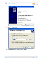
Page 21: ...reasons proceed according to instructions specified in the Troubleshooting chapter USB DRIVER INSTALLATION The installation procedure is described for Windows XP English locale The procedure is simila...

Page 22: ...WATTrouter ECO user manual www solarcontrols cz How to fit and setup the device Page 22 from 66 5 Select the path to the driver file 6 If the driver has been installed successfully this window appears...

Page 23: ...oller is turned on and connected to your computer Make sure that USB interface driver is correctly installed 3 Select correct port for connection This can be done in the dropdown menu Port in Serial p...

Page 24: ...wire is passing through the current sensing module in a reverse direction Use the Current orientation field for the relevant phase select the reversed option and press the Write button The configurat...

Page 25: ...act your electricity provider or use the each phase independently mode which works for any configuration of the energy meter In order to use the each phase independently mode it is necessary to select...

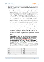
Page 26: ...ombiWATT mode provided a low tariff signal is connected to the controller it may be used even if single tariff rate is present see notes below This can be done on the Output settings tab CombiWATT mod...

Page 27: ...tion only supplies the preset minimum daily power to the boiler and thus making sure that there is enough warm water when the recommended configuration is used In cases when even under the recommended...

Page 28: ...that wireless devices will be accessible by the controller The accessible distance is based on construction of the building and it is possible to extend this range by repeaters Further information ca...

Page 29: ...button or you may load it at any time by pressing the Open button This way you may create several different configurations and monitor them for some time and determine which one provides better utili...

Page 30: ...le in the WATTconfig ECO control software and explains their meaning MAIN WINDOW The main window displays all basic measured values and statuses The controller can be configured using configuration ta...

Page 31: ...ion Imp pulse amount registered by FB input from the connection point This counters are not listed anywhere ImpkWh pulse amount per kWh see FB input configuration Impulses are counted only if the regu...

Page 32: ...e load as the power drawn by the connected load is not measured Energy counters inform CombiWATT mode or the corresponding time schedule about the energy already delivered to the load and at the same...

Page 33: ...e so that the measured currents are in phase with voltage Check the assignment using a control oscilloscope and a purely resistive thermal load on the given phase Note The Phase parameter replaces the...

Page 34: ...owing to a load or another appliance b Prod L1 input counts energy measured on L1 value will be added to daily production stats on L1 c Prod L2 input counts energy measured on L2 value will be added t...

Page 35: ...mode read the flicker recommendations in the Frequently Asked Questions section of the manufacturer s website c PWM only for SSR outputs or supported WLS outputs with activated SW package PWM mode for...

Page 36: ...g L1 L2 L3 output will be switched on behalf on average surplus energy from all 3 phases c Max L1 L2 L3 output will be switched on behalf on a maximum surplus energy from all 3 phases Within the assig...

Page 37: ...work correctly if heating coil No 1 is disconnected by the thermostat and the other two heating coils will continue producing heat In this scenario the relay will be continuously connected and disconn...

Page 38: ...I value the system may become unstable and this status may damage the connected device when there is no built in protection in the device PWM range since firmware version 1 7 these values can be used...

Page 39: ...l remain physically turned off This function in case of a relay output can be useful when you want to avoid delivering surplus energy to public grid Here typically one relay output is set as inverted...

Page 40: ...lus energy only if the Power field is set to 100 However it does not affect conditions for the activation of CombiWATT mode which then can run simultaneously with the enforcement mode Output enforceme...

Page 41: ...a relay output no longer exists a basic 10s delay is set for this output This delay is used to ensure impact free transition to the basic regulation mode Similar method is also used for proportional...

Page 42: ...t to switch on for a limited period of time Date and time settings Synchronize date and time with the client check this field if you want to synchronize the controller date and time with the actual ti...

Page 43: ...e is used to calculate the sunrise time and therefore values specified in degrees are precise enough Longitude enter the longitude in degrees here The value is used to calculate the sunrise time and t...

Page 44: ...xported to csv files Through current sensing module you can obtain only the consumption and surplus excess energy To display data on production and self consumption it is necessary to connect a pulse...

Page 45: ...nd consumption Charts in each phase indicate the part of corresponding summary data pie slice or part of the bar The self consumption value is calculated from the relationship self consumption product...

Page 46: ...e error list in the controller Save error list press this button to save the error list to a CSV file on your PC hard drive Clear log use this button to clear log contents Save log use this button to...

Page 47: ...several or no ports are shown check installation correctness of USB port in Windows device manager You can also find out there which port is used for this communication The communication parameters ar...

Page 48: ...ry values to the hard disk In case of problems consult an expert in IT Additional software features are bound to the serial number of the controller and they must be activated directly in the controll...

Page 49: ...e following way short short short L1 voltage is missing Proceed according to instructions specified in the chapter Measured parameters and statuses Flashes regularly in the following way long long sho...

Page 50: ...of 2 kW 200l of water average cold water temperature at the input is 12 C warm water target temperature 50 C average daily water consumption is 160 l The daily amount of electric power necessary to he...

Page 51: ...19 00 It becomes active only if the low tariff is available This allows you to heat up water for evening use provided that during morning and afternoon hours the boiler was not sufficiently heated up...

Page 52: ...ot sufficient amount of sunshine available the system will use the low tariff The motor should not be running at night between 23 00 and 5 00 not to disturb during night this also depends on the local...

Page 53: ...nsures the motor runs approximately 6 hours and therefore it applies only if the daily energy counter exceeds 1 8 kWh The second time schedule restricts operation of the motor between 23 00 and 5 00 w...

Page 54: ...as 1st priority relay No 2 requirements are the same as in example No 2 one heating coil with 2nd priority SSR 2 Connect the following to L3 phase auxiliary contact with 1st priority SSR 3 operating a...

Page 55: ...WATTrouter ECO user manual www solarcontrols cz How to fit and setup the device Page 55 from 66 Time schedules are the same as in example No 2...

Page 56: ...stem These heaters must be deactivated at summer time either through built in thermostats by deactivating fuse switches for respective outputs or by deactivating them in the software The heat pump dra...

Page 57: ...WATTrouter ECO user manual www solarcontrols cz How to fit and setup the device Page 57 from 66 Time schedules are the same as in example No 2...

Page 58: ...cable or try the cable with different device printer for example Computer cannot detect connected controller Check USB cable connection When USB device is being registered in your PC the yellow LED CO...

Page 59: ...shows approximate values or the status is not stable No defect Incorrect phase sequence or incorrect current orientation settings Follow the steps specified in the previous item Low tariff signal is...

Page 60: ...T production limit field which should be low You cannot load firmware even if you try repeatedly Incorrect or corrupted scf file Load only original firmware for the WATTrouter ECO device Communication...

Page 61: ...em to repair Wireless peripheral can t be registered even after longer period while connected Window Add wireless station is not displayed Station out of signal range Test the wireless peripheral so i...

Page 62: ...king with SC Gateway module is out of range The master controller with SC Gateway module does not communicate with SC Router module Activate the appropriate wireless output WLS in the master system so...

Page 63: ...ocess and heat dissipation of power SSRs Should you discover a defect which cannot be repaired according to instructions specified in the Troubleshooting chapter contact your distributor applies both...

Page 64: ...breaker type B External outputs for connection of solid state relays SSR S S1 S2 S3 S4 0 or 5 VDC isolated from power grid supply SSR parameters control DC min 4VDC SSR must switch at zero zero switch...

Page 65: ...6mm Overvoltage category III Electric strength 4 kV 1 min power supply L N output output output power supply current input external output etc GND I_L LT FB S S1 S2 S3 S4 Pollution degree 2 Operationa...

Page 66: ...ation relates is in conformity with the following directives standards and other normative documents provided that it is installed maintained and used in application for which it was made in accordanc...

Reviews: