WATTrouter ECO - user manual
www.solarcontrols.cz
How to fit and setup the device
Page 31 from 66
MEASURED PARAMETERS AND STATUSES
Measured values:
Power on ph. L… - the actual value of the active power measured on the relevant phase wire. Positive
value means production (PV-plant supplies power to the grid); negative value means that power is
being drawn from the grid.
Power sum L1+L2+L3 – sum of active power outputs in all three phases.
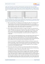
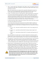
FB power- presents electric power, which is registered by pulse input. The value is calculated by
formula:
kWh
p
[s].Imp
t
3600
=
P[kW]
Where:
P – resulting power value (this box)
t
p
– period of impulses
Imp
kWh
– pulse amount per kWh (see FB input configuration)
The measurement dynamics depends on the impulse frequency. It may be very small for small
measured powers. The maximum measurable period of impulses is set to 15 seconds (at 1000
impulses per kWh it corresponds to output power value of 0.24 kW). If the measured power is lower,
zero is displayed.
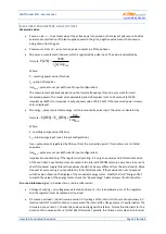
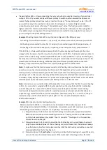
FB energy – presents electrical energy, which is counted by pulse input. The value is calculated by
formula :
kWh
p
Imp
Imp
[kWh]
E
=
E[kWh]
Where:
E - resulting energy value (this box)
E
p
– initial energy input (see. FB input configuration)
Imp – pulse amount registered by FB input from the connection point. This counters are not listed
anywhere.
Imp
kWh
– pulse amount per kWh (see FB input configuration)
Impulses are counted only if the regulator is operating. It is only an auxiliary and informative feature
of the controller. Counted impulses are saved in the internal EEPROM memory every hour. In case of a
short time power supply failure these values should not be very different from the actual reality. More
frequent impulse saving is not possible due to technical reasons. If these values do not correspond
with the value shown on the display of the connected energy meter, modify the field “Energy offset”
to match the value of the energy meter, check the "Reset energy"-field and press the Write button.
Error and info status
(gray in inactive status, red in active status):
Voltage L1 missing – no voltage was detected on phase L1 - this is a hardware error of the regulator
and the regulator must be replaced or repaired.
DC source overload – (since firmware version 1.7) voltage of the internal DC source drops below + 9V
relative to GND. This malfunction can occur when the internal DC voltage source is heavily loaded. The
firmware since version 1.7 checks this and eventually signals this failure. This malfunction lasts for the
duration of the cause and for a further 60s afterwards. Typically, this failure occurs when all 6 internal


