WATTrouter ECO - user manual
www.solarcontrols.cz
How to fit and setup the device
Page 41 from 66
Energy – if you mark this field, the time schedule activity additionally depends on the status of the
daily energy counter of the relevant output (the "Supplied energy" fields). Again the function differs
based on the time schedule mode:
a)
Restricted mode – the output will be restricted only if the daily energy counter exceeds the value
specified in the Limit field.
b)
Enforced mode– the output will be enforced only if the daily energy counter did not yet reach the
value specified in the Limit field.
Tip:
Time schedules may also be set for an output which does not have any assigned priority. These outputs may
be used for example, as time switch clock etc. Labels and "Connected power" field may be configured for these
outputs using the Output settings tab. "Connected power" field of such output is then used to update the daily
energy counter.
Note:
The conditions described above combine with logic AND within one time schedule. If you need to create a
logic OR combination, you need to add a second time schedule with the same time range and another condition.
For example, if the schedule should restrict the output function in case where the energy counter exceeds the
5 kWh limit AND the temperature at the assigned input exceeds 60 °C, just use one time schedule where both
conditions are set. If this should limit the output function in case where the energy counter exceeds the 5 kWh
limit OR the temperature at the assigned input exceeds 60 ° C, it will be necessary to use 2 time schedules with
the same time limits but each set for a different additional condition.
Note:
Impact-free transition to the basic regulation mode: If the condition necessary for the enforcement of a
relay output no longer exists, a basic 10s delay is set for this output. This delay is used to ensure impact-free
transition to the basic regulation mode. Similar method is also used for proportional outputs.
For more practical samples demonstrating configuration of time schedules, see the chapter Configuration
examples.
OTHER SETTINGS TAB
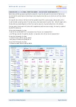
On this tab you may configure general control settings and other advanced device settings.
Control settings:
Control mode - it is used to set the basic control mode:
a.
Each phase independently - the controller will control outputs according to measured active
power on each phase wire separately. In this mode it is necessary to correctly set phases for all
active outputs. They must correspond with the phase wire where the load is connected to.
b.
Sum of all phases - the controller will control all outputs according to the sum of measured active
powers from all three phases. In this mode it is not necessary to set phases for individual outputs
as this does not matter.
Power offset – this field specifies the difference between the actual sum of measured powers in 3
phases L1+L2+L3 and the value used for the control purposes. For example, if the actual sum of
measured powers L1+L2+L3 equals to +500W and the power offset equals to -100W, the controller will
use the value of 400W to determine the conditions for output switching. Above terms apply for the
"sum of all phases" control mode. For the "each phase independently" control mode this power offset
value applies for each phase independently. The lower (more negative) the power offset is, the more
power consumption from grid is avoided in transitional statuses as well as in stable statuses where the
proportional outputs pass only small amount of power to the load. Transitional statuses are usually
identified by 4-quadrant energy meters as "movement around zero", where production and
consumption indicators change irregularly and fast. Negative power offset avoid showing up the

