WATTrouter Mx - user manual
How to fit and setup the device
Page 11 from 82
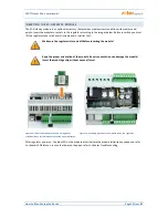
USB – communication light - USB interface (yellow)
ERR – error status light (red)
S1– external output for SSR 1 - activity indication light
S2– external output for SSR 2 - activity indication light
S3– external output for SSR 3 - activity indication light
S4– external output for SSR 4 - activity indication light
S5– external output for SSR 5 - activity indication light
S6– external output for SSR 6 - activity indication light
R1– relay output No. 1 - activity indication light
R2– relay output No. 2 - activity indication light
RJ45 connector – Ethernet connection indication light (left yellow LED – carrier frequency, right green
LED - connection speed)
Wireless PWR – SC-Gateway power LED (optional accessories)
Wireless LINK – SC-Gateway link LED (optional accessories)
Other connectors:
Micro SD – slot with integrated MicroSD card
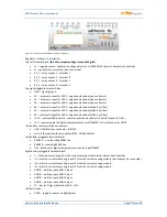
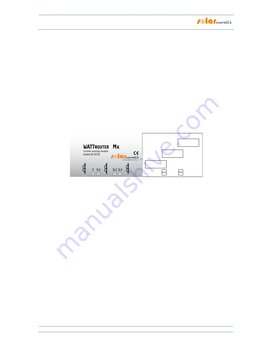
Figure 2: Connection terminals of current sensing module WT 02/10 (for WATTrouter Mx ) and WT 03/11 for WATTrouter Mx 100A. The
GND terminal of the WT 03/11 module must be connected to the Y terminal of the controller.
Current sensing module terminal description (the terminals are described directly on the motherboard of the
Mx 100A module):
Y– common wire (must always be connected), on the WT 03/11 module it is marked as GND.
I_L1 – current measuring output L1 (must be always connected)
I_L2 – current measuring output L2
I_L3 – current measuring output L3
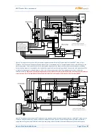
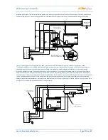
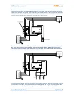
Connect the controller according to sample connection diagrams shown on figures below. If you observe basic
principles, connections may be combined in various ways. You may connect any number of loads to any
outputs; in certain cases you may remove certain phase cable from the measuring, etc.
GND
I_L1 I_L2
I_L3


