WATTrouter Mx - user manual
How to fit and setup the device
Page 15 from 82
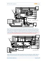
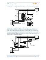
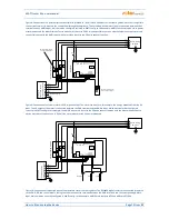
Figure 8: Connection of an external current transformer (marked as TR, this may be another current sensing module or other compatible
current transformer) to measure the current flow through the appliance. The secondary transformer circuit is connected between the Y
terminal and any ANDIx input, which must be configured correctly in WATTconfig. In this example, ANDI1 function must be set to power
measurement and the Measurement Source option must be set to SSR1. It is also possible to use an external impulse output meter and
connect this output to the ANDI input, which must then be set to the S0 pulse counter function.
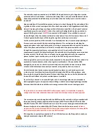
Figure 9: Connection of external meter with S0 impulse output. The meter can measure, for example, the energy produced from the PV
plant. The S0 output of the meter is connected between the GND terminal and the ANDIx input, which must be further configured
correctly in WATTconfig. In this example, the ANDI1 input must be set to the S0 pulse counter function, and the Measurement Source
option must be set to one of the Lx items if the meter measures the PV power produced.
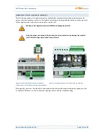
Figure 10: Connection of supported types of temperature sensors to the regulator. The DS18x20 digital sensors are connected three-wire
to the GND, DQ and +5V terminals, analog sensors are connected two-wire between the GND terminals and the corresponding ANDIx
input, which must be correctly configured in WATTconfig. In this example, ANDI3 must be set to NTC and ANDI4 to PT1000.
L1
C
ur
re
nt
s
ens
ing
m
od
u
le
N
R
eg
ul
at
or
IL
1
IL
2
IL
3
B DQ
Y
LT
A
ND
I3
A
ND
I4
A
ND
I2
R2_
1
R2_
2
L1
N
A
ND
I1
R1
_1
R1
_2
IL
3
IL
2
IL
1
Y
House wiring
+ PV plant
PE
PE
Pub
lic
g
ri
d
co
n
ne
ct
io
n
po
in
t
(m
ai
n
ene
rg
y
m
et
er
)
Wire goes through
current transformer
LT (low tariff signal)
I >
B6A
USB
LAN
micro
SD
G
ND
S2
-
S1
-
S4-
S3-
S6
-
S5-
+
12
V
+
5V
A
RS485
L2
L3
L1
N
L2
L3
Auxilliary energy meter
with S0 impulse output
L1
C
ur
re
nt
s
ens
ing
m
od
u
le
N
R
eg
ul
at
or
IL
1
IL
2
IL
3
B DQ
Y
LT
A
ND
I3
A
ND
I4
A
ND
I2
R2_
1
R2_
2
L1
N
A
ND
I1
R1
_1
R1
_2
IL
3
IL
2
IL
1
Y
House wiring
+ PV plant
PE
PE
Pub
lic
g
ri
d
co
n
ne
ct
io
n
po
in
t
(m
ai
n
ene
rg
y
m
et
er
)
LT
I >
B6A
USB
LAN
micro
SD
G
ND
S2
-
S1
-
S4-
S3-
S6
-
S5-
+
12
V
+
5V
A
RS485
L2
L3
L1
N
L2
L3
DS18x20
NTC
PT1000


