background image

WATTrouter Mx - user manual 


How to fit and setup the device 

Page 29 from 82 


DESCRIPTION OF WATTCONFIG MX ITEMS 

This chapter contains a list of all items available in the WATTconfig control software and explains their 
meaning. Or you may use the controller web interface, where the items have identical names and meanings. 

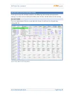
MAIN WINDOW 

The main window displays all basic measured values and statuses. Controller can be configured using 
configuration tabs.  


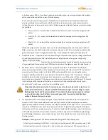
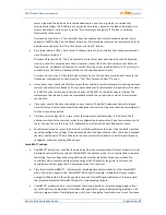
Figure 17: Main window of WATTconfig software. 


Summary of Contents for WATTrouter Mx

Page 1: ...device Page 1 from 82 WATTROUTER MX USER MANUAL FOR MODELS WATTROUTER MX WRMX 01 08 17 AND WT 02 10 WATTROUTER MX 100A WRMX 01 08 17 A WT 03 11 HOW TO FIT AND SETUP THE DEVICE Document version 1 1 La...

Page 2: ...figuration 27 Wireless comunication settings 27 Finishing the configuration 28 Description of WATTconfig Mx items 29 Main window 29 Measured parameters and statuses 30 Input settings tab 33 Output set...

Page 3: ...Ethernet network configuration 61 Local network connection settings 61 Setting up Internet access 62 Description of web interface and XML communication 63 Troubleshooting 72 Maintenance and repairs 7...

Page 4: ...n of resistive loads compliant to European standards EN 61000 3 2 and EN 61000 3 3 This regulation modulates connected load s power exactly according to the available surplus energy Very short average...

Page 5: ...ximum power the system waits until the power output of PV plant increases again beginning of dawn If electric production is determined even when this load is switched on load with second priority in t...

Page 6: ...the device Page 6 from 82 This device is not designed for precise active power measurement it is not a replacement for a wattmeter or electricity meter Active power is measured with sufficient precis...

Page 7: ...o fit and setup the device Page 7 from 82 PACKAGING CONTENTS Contents of packaging 1 WATTrouter Mx regulator 1 WATTrouter Mx current sensing module 1 USB cable 1 short manual with links to this manual...

Page 8: ...direct sunlight and the ambient temperature must be maintained within the range mentioned in chapter Technical specifications Do not place the regulator or other electronic components of this system n...

Page 9: ...le with cross section from 0 5 to 1 5 mm 2 If these wires are longer than 2m or are placed in a cable tray together with other power cables wires we recommend using a shielded cable Similar recommenda...

Page 10: ...t for SSR 6 negative electrode Sallen Key filter 12V external SSR outputs common positive electrode 12V with respect to GND 5V power supply for digital temperature sensors DS18x20 5V with respect to G...

Page 11: ...LINK SC Gateway link LED optional accessories Other connectors Micro SD slot with integrated MicroSD card Figure 2 Connection terminals of current sensing module WT 02 10 for WATTrouter Mx and WT 03 1...

Page 12: ...nded SSR RGS1A series manufactured by Carlo Gavazzi L1 Current sensing module N Regulator IL1 IL2 IL3 B DQ Y LT ANDI3 ANDI4 ANDI2 R2_1 R2_2 L1 N ANDI1 R1_1 R1_2 IL3 IL2 IL1 Y Load 1 only resistive Hou...

Page 13: ...ctual surpluses L1 Current sensing module 1 N Regulator IL1 IL2 IL3 B DQ Y LT ANDI3 ANDI4 ANDI2 R2_1 R2_2 L1 N ANDI1 R1_1 R1_2 IL3 IL2 IL1 Y Load 1 only resistive House wiring PE PE Wire goes through...

Page 14: ...ose we recommend using lines which are not overrated for the nominal secondary current just to be able to make more turns through the hole of measuring transformer When connected through external curr...

Page 15: ...be set to the S0 pulse counter function and the Measurement Source option must be set to one of the Lx items if the meter measures the PV power produced Figure 10 Connection of supported types of temp...

Page 16: ...an external power source as shown in the figure Firmware since version 1 5 already checks the voltage drop at 12V terminal and also enables software optimization of the built in relay consumption For...

Page 17: ...e inputs must be set up correctly in the WATTconfig control software We strongly advise you to protect your loads connected to the power SSRs with fuses suitable for protection of semiconductors rathe...

Page 18: ...nnect the load for low power of SSR output in this scenario the built in fan s power is not sufficient to cool down the heating element of the load Therefore consider fitting these loads to SSR output...

Page 19: ...milar tool Make sure the regulator is turned off before inserting the module Keep the proper orientation of the module Reverse orientation can damage the module Insert the module gently without unusua...

Page 20: ...low and if there is no conflict between IP addresses or conflict between physical MAC addresses Tip The controller can be monitored and configured via the RS485 interface using the WATTconfig Mx softw...

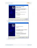
Page 21: ...r Mx user manual How to fit and setup the device Page 21 from 82 4 Select No not this time In the following window select Install from a list or specific location Advanced 5 Select the path to the dri...

Page 22: ...the installation there might appear a warning about an invalid digital driver signature Just ignore it The device is registered in your system device manager as USB serial converter menu Universal Ser...

Page 23: ...the Input settings tab First you set the phase sequence and then the direction of current flows through the current sensing module a Setting up phase sequence Turn off the PV plant and turn on a resis...

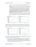
Page 24: ...t is fitted correctly sine wave of the current flowing through a resistive heat load is in phase with the voltage WATTconfig shows negative values on selected phase consumption Left image appears when...

Page 25: ...st highest priority is switched on The switching time is different for proportional outputs their function equals to proportional or PWM and relay outputs Proportional outputs are switched on almost i...

Page 26: ...e actual delivered energy the boiler thermostat may shut it off at any time If you want to count only real supplied energy to the boiler then connect additional measurement for it according to Figure...

Page 27: ...you don t have double tariff rate or the signal cannot be utilized but you still want to use the CombiWATT mode connect the GND terminal to the LT terminal In such scenario the low tariff signal will...

Page 28: ...ld be registered 3 Upon closing the Add wireless station dialog see Fig Other Settings tab press the Write button The configuration will be saved in the controller 4 On the Output settings tab assign...

Page 29: ...tems available in the WATTconfig control software and explains their meaning Or you may use the controller web interface where the items have identical names and meanings MAIN WINDOW The main window d...

Page 30: ...temperature sensor ANDI or DQ input but this sensor does not work Change the time schedule configuration or fix the problem with the sensor DC source overload Voltage level at terminal 12V drops belo...

Page 31: ...mount of delivered energy Counters are reset to zero based on the configuration of CombiWATT Energy counter reset field in the Other settings tab Note In case ad a the WATTrouter device does not know...

Page 32: ...ower supply failure these values should not be very different from the actual reality More frequent impulse saving is not possible due to technical reasons If these values do not correspond with the v...

Page 33: ...transformers Do not overload the ANDI inputs with bigger primary currents than 15A which corresponds to secondary current 15mA b S0 pulse counter connect impulse output S0 of an external meter which m...

Page 34: ...vailable a Unknown input counts e g energy flowing to a load or another appliance b Prod L1 input counts energy measured on L1 value will be added to daily production stats on L1 c Prod L2 input count...

Page 35: ...ch will vary according to the assigned input function a Power measurement one whole period of measured current is displayed the value for zero measured power should be around 2000 digits For more info...

Page 36: ...assign a label for the relevant output Label may contain a maximum of 16 characters in ASCII encoding Priority it is used to set priority for the relevant output First priority is the highest the eig...

Page 37: ...mple due to limited SSR cooling possibility or due to saving the surplus energy for additional outputs you may decrease this value The value in the Load power field may be slightly lower than the sele...

Page 38: ...verall power power drawn by the first coil surplus energy exceeds the value of Connected power field set for relay No 1 In this case the part of surplus energy will be still delivered to public grid a...

Page 39: ...frequently The value may be decreased down to 2s However such small delay time may sometimes cause false load switching Therefore we recommend decreasing the value only in certain cases and after pro...

Page 40: ...s may worsen the energy efficiency of your facility Setting up time schedules depends entirely on your creativity and provides a wide range of different combinations Only advanced users should use tim...

Page 41: ...eeds the value specified in the Limit field b Enforced mode the output will be enforced only if the daily energy counter did not yet reach the value specified in the Limit field Temperature if you mar...

Page 42: ...applies for each phase independently The lower more negative the power offset is the more power consumption from grid is avoided in transitional statuses as well as in stable statuses where the propor...

Page 43: ...cally routed to this IP address Controller MAC address physical MAC address of the controller Change this address only if there is a conflict between physical addresses in your local network UDP port...

Page 44: ...e zone based on your country The default value uses Central European time This value is only used to modify the calculated sunrise time Time zones outside of multiples of full hours are not supported...

Page 45: ...specified in degrees are precise enough Tip By changing the longitude you may modify the sunrise time in order to reset energy counters according to your preferences for example based on how large ar...

Page 46: ...again at any time after your power is restored If possible download your firmware via USB or ONLY from your local network should an error occur during the download the controller remembers the origin...

Page 47: ...the values in the fields Supplied energy reset of those fields is generally done at different time Daily ANDI input status displays the measured energy at corresponding ANDI input in the current or s...

Page 48: ...input in the current or selected day Total L1 L2 L3 displays summary data from all three phases The calculation of these data depends on the selected control mode the Control mode field on the Other s...

Page 49: ...oads configuration from the controller just after successful connection has been established Disconnect disconnects your computer from the controller Configure connection the software displays a windo...

Page 50: ...ile may be created by pressing the New button The new profile stores the current IP address and UDP port settings Created profiles may be deleted by the Delete button IP address IPv4 IP address used t...

Page 51: ...ss or at least often unchanging dynamically allocated IP address as is in the case of standard access to the controller from outside the Internet Feature configuration Server hostname enter domain nam...

Page 52: ...t L1 Proceed according to instructions specified in the chapter Measured parameters and statuses Flashes regularly in the following way short short long Temperature sensor s error Proceed according to...

Page 53: ...at up the entire boiler without taking into account heat losses is kWh K T l V c E V 82 8 3600000 38 200 4180 3600000 Average daily losses of boilers with these parameters represent approximately 1 5...

Page 54: ...oreover until the supplied energy to the boiler did not exceed the specified limit This allows you to heat up water for evening use provided that during morning and afternoon hours the boiler was not...

Page 55: ...ould not be running at night between 23 00 and 5 00 not to disturb people during night this also depends on the local low tariff time schedule so that the motor can get a chance to run If the boiler i...

Page 56: ...mately 6 hours 1 8kWh 0 3kW and therefore it applies only if the output energy counter field Supplied energy exceeds 1 8 kWh The second time schedule restricts operation of the motor between 23 00 and...

Page 57: ...e same as in example No 2 Again we can set the Prepend before SSR condition to make better use of PV surpluses Connect the following to L2 phase heating pump has 1st priority relay No 2 Requirements a...

Page 58: ...WATTrouter Mx user manual How to fit and setup the device Page 58 from 82 Time schedules are the same as in example No 2...

Page 59: ...se switches for respective outputs or by deactivating them in the software The heating pump draws power of 1 3 kW and it is powered only with the PV surplus energy or manually independently of the WAT...

Page 60: ...WATTrouter Mx user manual How to fit and setup the device Page 60 from 82 Time schedules are the same as in example No 2...

Page 61: ...tings tab group Network settings Network configuration changes will become effective only after you reset the regulator see option Reset unit on config write IP address enter the IP address where regu...

Page 62: ...nslate global IP addresses and ports into local network IP addresses ports The following text describes a sample Internet connection configuration using a regular broadband router Edimax BR 6204Wg M S...

Page 63: ...nternet browser by using AJAX XML technology and therefore you have to allow JavaScript Monitoring the controller activity and configuring it may also be implemented into any superior control system c...

Page 64: ...d by time schedule 0 inactive 1 active HR 0 HR output restricted by time schedule 0 inactive 1 active T 0 T output test 0 inactive 1 active O1 similarly for remaining outputs SSR2 O2 to WLS6 O14 DQ1 2...

Page 65: ...um output power in kW PN 0 00 PN minimum output power in kW only for PWM function PI 500 PI PWM I value only for PWM function TO 15 TO on delay time in s only for relay function TF 15 TF off delay tim...

Page 66: ...the controller This configuration has the same format as the GET conf xml command but you must can also send additional data Append the configuration to the POST conf xml command and skip 1 empty line...

Page 67: ...learn LRN 1 LRN search for temperature sensors UN admin UN username for authorization mandatory item UP 1234 UP password for authorization mandatory item learn The controller will reply with the follo...

Page 68: ...ly for the 2th to 7th last day stat_week 8 GET stat_month xml By sending this HTTP request you will obtain the monthly statistics from the controller Structure of returned data Response headers one em...

Page 69: ...odically transmitted XML data record to the server in the example shown this record is being processed by index php on the server POST index php HTTP 1 1 Request headers one empty line wrmx meas DaR 2...

Page 70: ...mption normal tariff phase L1 in kWh SDL1 0 00 SDL1 consumption low tariff phase L1 in kWh SDP1 0 00 SDP1 production phase L1 in kWh similarly for remaining phases L2 and L3 SDS4 0 00 SDS4 surplus ene...

Page 71: ...WATTrouter Mx user manual How to fit and setup the device Page 71 from 82...

Page 72: ...tage Check whether green LED PWR is on and the regulator is powered Computer is not properly connected with the regulator Check the USB network cable connection try using different network cable or tr...

Page 73: ...local network or Internet connection is temporarily out of order overloaded with other transfers etc Try to reconnect later or ask a network expert for advice to optimize your connection Regulator fai...

Page 74: ...active Wait until the signal is active or manually test the auxiliary relay by switching it on some relays offer this option Regulator failure defect Replace the regulator or take it to repair ANDI in...

Page 75: ...rminal 5V with a milliammeter the input current should match the sensor specification i e max 2mA A faulty sensor sometimes has an increased power consumption and is warming up this is not a rule If t...

Page 76: ...ecessarily all connected proportional outputs with higher priority may be disconnected earlier than the relay outputs with lower priority CombiWATT function runs even if PV plant produces power This i...

Page 77: ...s problem with technical support Station is incompatible It is different type of wireless peripheral which is not compatible with SC Gateway module Station is defective Follow the installation manual...

Page 78: ...d heat dissipation Should you discover a defect which cannot be repaired according to instructions specified in the Troubleshooting chapter contact your distributor applies both to warranty and post w...

Page 79: ...60 mA depending on load this voltage can drop to 8V 5V terminal 5V with respect to GND Max cons 100 mA It is used to connect external semiconductor relays common positive anode or as power supply for...

Page 80: ...power grid supply Power measurement function as inputs IL1 to 3 but approx 15 mA S0 pulse counter function 0 or 5 V with respect to GND Minimum pulse and gap width is 1ms NTC function Supported is res...

Page 81: ...strength 4 kV 1 min between power supply L1 N and pluggable terminals between power supply and relay outputs R1 and R2 between power supply and communication sockets Pollution degree 2 Operational te...

Page 82: ...declaration relates is in conformity with the following directives standards and other normative documents provided that it is installed maintained and used in application for which it was made in acc...

Reviews: