WATTrouter Mx - user manual
How to fit and setup the device
Page 30 from 82
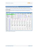
MEASURED PARAMETERS AND STATUSES
Measured values:
Power on ph. Lx - the actual value of the active power measured on the relevant phase wire. Positive
value means production (PV-plant supplies power to the grid); negative value means that power is
being drawn from the grid.
Power sum L1+L2+L3 – sum of active power outputs in all three phases.
Voltage at L1 – voltage on phase L1 which powers up the regulator. This voltage value is used to more
accurately calculate the power output than for the older WATTrouter models where the voltage was
not measured and a constant value of 230V was assumed. It is also used for calculating the powers on
other phases where a similar voltage value is assumed.
Error and info status
(gray in inactive status, red in active status):
Missing voltage L1 – failure of the synchronization circuit that detects the voltage at L1 terminal. This
is a hardware failure of the regulator and it must be replaced or repaired.
Wrong voltage value L1 - grid voltage is too low (<200VAC) or high (> 260VAC). Firmware since version
1.5 signals this fault separately from the previous general state "Missing voltage L1". The controller
will remain functional in this malfunction state, only indicating the problem. Instead of the measured
voltage value, a fixed voltage of 230VAC is assumed (as for previous models CWx, M, ECO). If the
voltage at terminal L1 is within the specified limits, it is a circuit failure that measures the voltage, and
replacement or repair of the controller is recommended.
Temperature sensor(s) – somewhere in time schedules temperature conditions are defined according
to a temperature sensor (ANDI or DQ input) but this sensor does not work. Change the time schedule
configuration or fix the problem with the sensor.
DC source overload - Voltage level at te 12V drops below + 9V relative to GND. This
malfunction can occur when the internal DC voltage source is heavily loaded. The firmware since
version 1.5 checks this and eventually signals this failure. This malfunction lasts for the duration of the
cause and for a further 60s afterwards. Typically, this failure occurs when all 8 internal outputs are
used or there is overload on the + 12V or + 5V terminals may (there can be for example a malfunction
of some digital sensor if powered from + 5V terminal). Please check that the + 12V or + 5V terminals
are not overloaded. When the two internal relays are occupied, connect the control circuits of all used
SSRs to an external source (see Figure 12). You can also enable the Optimize internal relay
consumption feature (see chapter Other settings tab) which might help to reduce the power
consumption of internal relays.
Low tariff – if the low tariff signal is detected the red light comes on, otherwise it is grayed.
Summer time - informs the user that the summer time mode is active. Summer time starts at 2:00 CET,
on the last Sunday in March and ends at 3:00 CEST, on the last Sunday in October. If the option "Use
summer time" is not marked on the "Other settings" tab, the indicator remains inactive.
CombiWATT is active – informs the user that CombiWATT mode is active. This indicator is active if the
condition necessary to run CombiWATT is valid, if the low tariff is active and if the CombiWATT
function has been configured for some output.
Output test is active – informs the user about a status when some of the outputs have been activated
by the TEST button. Output tests done via LAN interface are protected from unauthorized access or
intervention.


