WATTrouter Mx - user manual
How to fit and setup the device
Page 42 from 82
transition to the basic regulation mode. Similar method is also used for proportional outputs. User-defined off-
delay time is not used here.
For more practical samples demonstrating configuration of time schedules, see the chapter Configuration
examples.
OTHER SETTINGS TAB
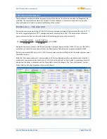
On this tab you may configure general control settings and other advanced device settings.
Control settings:
Control mode - it is used to set the basic control mode:
a.
Each phase independently - the controller will control outputs according to measured active
power on each phase wire separately. In this mode it is necessary to correctly set phases for all
active outputs. They must correspond with the phase wire where the corresponding load is
connected to.
b.
Sum of all phases - the controller will control all outputs according to the sum of measured active
powers from all three phases. In this mode it is not necessary to set phases for individual outputs
as this does not matter.
Power offset – this field specifies the difference between the actual sum of measured powers in 3
phases L1+L2+L3 and the value used for the control purposes. For example, if the actual sum of
measured powers L1+L2+L3 equals to +500W and the power offset equals to -100W, the controller will
use the value of 400W to determine the conditions for output switching. Above terms apply for the
"sum of all phases" control mode. For the "each phase independently" control mode this power offset
value applies for each phase independently. The lower (more negative) the power offset is, the more
power consumption from grid is avoided in transitional statuses as well as in stable statuses where the
proportional outputs switch only small amount of power to the load. Transitional statuses are usually
identified by 4-quadrant energy meters as "movement around zero", where production and
consumption indicators change irregularly and fast. Negative power offset avoid showing up the
consumption indicator, but during normal and stable control statuses some surplus energy flows
unused into public grid. If you use standard connection and configuration, then it is not recommended
to use positive offset.
PWM frequency - set the desired frequency for outputs with PWM function. This frequency is always
the same for all outputs (and cannot be set differently by hardware). If the slow rate is set, the analog
outputs SSR4 to SSR6 will have a significant output ripple. Therefore, if the SSR1 to SSR3 outputs are to
be set at a slow frequency and the SSR4 to SSR6 outputs must have a small ripple, then this ripple
must be eliminated by an additional RC filter.
Voltage calibration - it is used to calibrate the voltage measured at the L1 phase. If the measured
voltage differs from the reality by more than about 3V you can calibrate it by specifying the multiplier
and the divider in the same way as for the External MT conversion ratio, see chapter Input settings
tab. For example, a 100:99 calibration increases the measured value by about 2 V, whereas a 99:100
calibration will decrease it.
By entering incorrect values, the voltage value may go beyond the specified limits (200V to 260V)
and the Missing voltage L1 error is emitted!


