12
EN
G
LI
SH
Disconnecting DC connections from the inverter
Disconnect DC cables according to the manufacturer's instructions. A special
tool is required for this.
Warning
DC cables are under current if light falls on the modules.
Disconnecting the AC plug from the inverter
For the Turbo 1P Mini / 1P inverter:
1. Remove the AC plug from the socket on the inverter as described in chapter 13.1.
2. Check that all pins of the AC plug are free of voltage. Use a suitable voltmeter for
this (do not use a simple neon phase checker).
For the Turbo 3P1 / 3P2 inverter:
1. Disconnect the AC plug from the inverter: gently press in the ratchet near the
front of the AC plug with a suitable object to unlock it, and remove the plug.
2. Check that all pins of the AC plug are free of voltage. Use a suitable voltmeter for
this (do not use a simple neon phase checker).
Opening the AC plug (only if required)
For the Turbo 1P Mini / 1P inverter:
Open the AC plug as described in the Appendix under Mounting > AC plugs.
For the Turbo 3P1 / 3P2 inverter:
Open the AC plug: First open the cable gland at the back and then push in the
ratchets on the left and right of the plug casing (simultaneously) and unlock
with a suitable tool. Then remove the upper part of the casing from the con-
tact part.
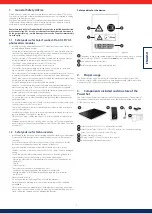
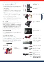
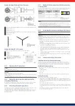
Removing the inverter from the mounting plate
1. Use one hand to press the retaining plate on the mounting plate approx.
5 mm (0.20 in) towards the mounting surface
1
(Figure 30).
2. Use the other hand to push the inverter upwards, far enough so that the
retaining plate no longer latches.
2
Release the retaining plate.
3. Lift the inverter with both hands until the hooks on the rear side of the inverter
are free
3
4. Remove the inverter from the mounting surface
4
3
1
2
4
Figure 30
6.
Structure and function of the Turbo inverter
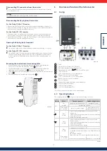
6.1 Casing
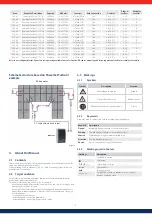
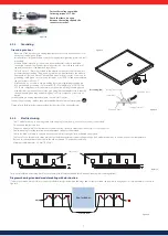
Figure
31
1
Hood
2
Display (monochrome, 128 x 64 pixels)
3
Type plate, Serial number, warning notices
4
Operating buttons:
ESC
, , ,
SET
(from left to right)
5
1x AC connector
6
1x DC connector plus (+) for solar modules
(Phoenix Contact SunClix, insulated)
7
1x DC connector minus (−) for solar modules
(Phoenix Contact SunClix, insulated)
8
DC circuit breaker
(interrupts plus and minus inputs simultaneously)
9
2x RJ45 sockets (RS485 bus)
10
1x RJ45 socket (Ethernet)
11
1x RJ10-socket (Modbus RTU)
The casing components are described in detail below.
6.2 Operating buttons
The operating buttons (
4
in Figure 31) have the following functions:
Button
Action
Function general
Guided configuration
ESC
Press
briefly
jumps up by 1 menu level
navigates 1 step
discards any changes
Press longer
(≥ 1 second)
jumps to status display
jumps to the start of the
guided configuration process
Press
briefly
• moves the highlighted bar or the content of the
display up
• moves the highlighted position in a numerical setting
one digit to the left
• increases a setting by one step
Press
briefly
• moves the highlighted bar or the content of the
display down
• moves the highlighted position in a numerical setting
one digit to the right
• decreases a setting by one step
SET
Press
briefly
jumps down 1 menu level
–
• a selected numerical value begins to flash and can be
altered
• adopts any changes
• alters the state of a control (checkbox/radio button)
Press longer
(≥ 1 second)
answers a query dialogue with yes navigates 1 step forward
Table 1

