14
EN
G
LI
SH
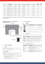
6.5 Troubleshooting
Faults are indicated by event messages as described below. The display flashes red.
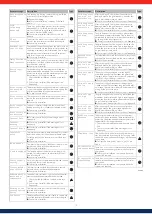
Table 2 "List of event messages" contains information on troubleshooting and fault
correction.
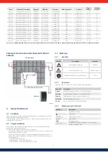
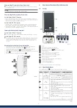
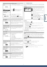
Structure
2
3
5
4
6
1
Event messages have the following information:
1
Symbol for the type of event message
2
Date/time when the event occurred
3
ACTIVE
= The cause of the event message is
still present or
date/time
when the cause of the event
message was corrected.
4
Cause of the event message:
5
Counter:
No, of the displayed event message/
Total number of event messages
;
max. total number of
event messages
= 30
6
NEW
is displayed until the event message is
confirmed using
ESC
or
.
Function
Event message types
•
Type Information (Symbol )
The inverter has detected an error that does not affect the feed-in process.
The user does not need to intervene.
•
Type Warning (symbol
)
The inverter has detected an error that may result in reduced yields. It is highly
recommended that you correct the cause of the error.
•
Type Error (Symbol
)
The inverter has detected a serious error. The inverter will not feed into the grid
while this error is present.
Please contact your installer. More information is provided in table 6 “List of
event messages.”
Display behaviour
New event messages are displayed immediately. The messages disappear after they have
been confirmed or their cause(s) have been corrected.
Advice
When an event message is confirmed, the user thereby simply confirms that he/
she has seen the message. This does not correct the error that caused the event
message to be shown!
If messages exist whose cause has been corrected but which have not been
confirmed then
is shown in the status display. If an already confirmed error
recurs then it is displayed again.
Operation
Confirming event messages
√
An event message with the comment
NEW
is displayed.
Press
ESC
/ / . The event message is confirmed.
Displaying event messages
1. Select
Event log
in the main menu.
2. Press
SET
. The event messages are displayed in chronological order (latest
message first).
3. Press
to page through the
Event Messages
.
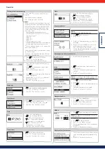
Calling up the service menu and editing the values
1. Select the
Service
menu item.
2. Press
SET
. The fig. shown at the left appears.
3. Press
simultaneously for 3 seconds.
The service menu is displayed (fig. left).
4. Press
to select a menu item.
5. Press
SET
to go into the menu item.
The following applies:
• Enter the password if required (fig. left).
• Within a menu item press
if required to dis-
play and alter further settings (e.g., voltage limits).
• - The menu items are described in section 9.3.4.
Power limiting
The inverter's output power can be restricted
manually to a minimum of 500 W. If the power is
manually restricted, the symbol
Derating
and the
reading
Derating/reason
:
User default
are displayed in the status display.
Delete country setting
After the country setting has been deleted, the
device restarts and displays the guided initial
commissioning menu.
Factory setting
Resetting the device to the factory setting de-
letes the following data:
• Yield data
• Event messages
• Date and time
• Country setting
• Display language
• Network settings
After the factory setting has been deleted, the
device restarts and displays the guided initial com-
missioning menu.
Voltage limits (peak values)
The following voltage limits can be changed:
• Upper disconnection value
1
)
• Lower disconnection value
1)
(figure left)
1)
The disconnection value refers to the peak value
of the voltage.
Frequency limits
The following frequency limits can be changed:
• Upper disconnection value.
• Lower disconnection value (figure left)
• Derating switch-on threshold (because fre-
quency is too high)
• Frequency threshold when switching on again.
Voltage limits Ø (average value)
The following voltage limits can be changed:
• Upper disconnection value
1)
(Figure left)
• Lower disconnection value
1)
• 1)
The disconnection value refers to the average
value of the voltage.

