23
13. Appendices
13.1 AC plug for Turbo inverters
Important information – please read carefully
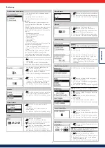
This sheet describes how to mount two-pole and three-pole
gesis
RST connec-
tors. Please note that electrical connection and installation must only be carried
out by suitably trained technical professionals.
Range of application and ignition protection class
•
II 3 G Ex nA II, 80°C (T6)
•
II 3 D Ex tD A22 T 85 °C (H05VV-F…: T 70 °C; H07RN-F…: T 60 °C)
Certificate No SEV 07 ATEX 0110 X
Wider range of application for the following device connections and initial con-
nections using screws:
• RST20I3S(D)S1 ZR.. / ..S(D)B1 ZR..
• RST20I3S(D)S1 M.. / ..S(D)B1 M..
See "Special conditions X"
Cable types
• H05VV-F… 1.5 mm
2
and 2.5 mm
2
• H07RN-F… 1.5 mm
2
and 2.5 mm
2
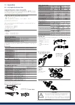
Technical specifications
Rated voltage
50 V, 250 V, 250/400 V
Rated cross-sectional area
2.5 mm
2
(0.0038 in²)
Degree of protection
IP 66/68
Single stranded wires and fine stranded wires of 0.75 mm² and 1.0 mm² may also
be clamped
Rated current
Device connections and initial connections using screws and spring-cage
connections
1.5 mm
2
(0.0038 in²)
2.5 mm
2
(0.0038 in²)
16 A
20 A
Assembled cables
Cable type
H05VV-F
H07RN-F
1.5 mm
2
(0.0038 in²)
16 A
14.5 A
2.5 mm
2
(0.0038 in²)
20 A
17.5 A
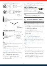
Connectable cross sections (mm
2
)
min.
max.
Screw
1.5
4
Spring-cage
1.5
2.5
Connectable conductor types
Conductor cross-sec-
tion (mm
2
)
Screw-type terminal Single stranded/fine stranded 1.5...2.5
– also
Fine stranded
4.0
– also
Flexible with ferrule
1.5...2.5
Screwless terminal
Single stranded
1.5...2.5
– also
Flexible with ultrasound
sealed conductor ends
1.5...2.5
– also
Flexible with ferrule
1.5
Crimp connection
Flexible with ultrasound
sealed conductor ends
1.5...2.5
Number of cables per terminal: 1 or 2
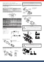
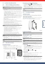
Cable and wire stripping lengths (mm)
Crimping pliers for
ferrules: Product no
95.101.1300.0
Spring-cage connectors
Conductor
PE
N,L
PE
N,L
Single connector
Double connector
Cable stripping length (mm)
40
35
55
50
Wire stripping length x (mm)
Conductor cross-section (mm
2
)
1.5
2.5
Single stranded
14.5+1
14.5+1
Fine stranded (only with ferrule)
13+1
Ferrule complies with DIN 46228-E-…
12
Ultrasound sealed
14.5+1
14.5+1
Screw connections
Cable strain relief
ø10…14
ø13…18
Conductor
PE
N,L
PE
N,L
Cable stripping length (mm)
Single connector
30
25
42
37
Double connector
45
40
Wire stripping length x (mm)
8
(conductor cross-section 1.5…4 mm
2
)
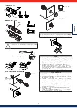
Bending radii
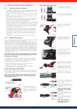
Please comply with the minimum bending radius of the conductor. Avoid traction
on the contacts by:
1. Bending the conductor as
required
2. Cutting the conductor to
length
3. Stripping the cable and
wires.
Mounting the conductors
Spring-cage connector
Screw connector:
PZ1 screwdriver,
tightening torque
typ. 0.8…1 Nm
Locking
Screwing to-
gether:
Tightening torque
typ. 4+1 Nm
Mating and locking
ATTENTION
• The connectors should not be used to interrupt the power.
Never connect or disconnect them when the power is on!
• Protective caps (accessories) must be fitted on all exposed plug
and socket components to guarantee compliance with the IP
protection class.

