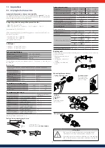
26
EN
G
LI
SH
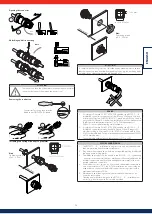
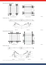
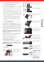
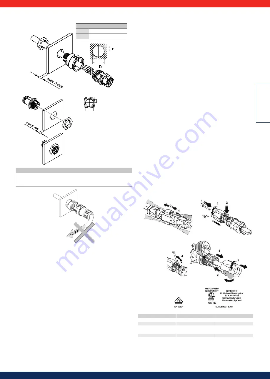
Installing the casing with an M16 and M20 grommet
Nut:
Tightening torque
typ. 2.5…3 Nm
r (mm)
D (mm)
M16
6.8-0.2
17 ± 0.15 mm
M20
8.7-0.2
21 ± 0.15 mm
Installing the casing with an M25 grommet
11.7 -0.2 mm
Nut:
Tightening torque
typ. 2.5…3 Nm
ø 25.5 ± 0.15 mm
ATTENTION
To comply with the IP68 protection class take appropriate measures to ensure
that the connectors are protected from bending forces (e.g., do not hang loads
on cables, do not leave the cable rewind hanging etc.)
13.2 SunClix connectors
SUNCLIX photovoltaic connectors for use in photovoltaic systems with 2.5-5 mm
2
solar cables of type PV1-F or UL approved solar cables (ZKLA), AWG 10-14
1 Safety precautions
WARNING:
The SUNCLIX connectors must only be connected by persons trained
in electrical engineering.
WARNING:
Never connect or disconnect the SUNCLIX connectors when the
power is on.
Attention:
Only use these connectors with a 2.5-6 mm
2
solar cable of type PV1-F
or UL approved solar cable (ZKLA copper strand, AWG 10-14) Only using this
cable will ensure a safe electrical connection. Other cable types are possible on
request. When laying the cable pay attention to the bending radii specified by the
manufacturer.
ATTENTION:
Only connect this plug with other SUNCLIX connectors. It is essen-
tial that you pay attention to the information on rated voltage and rated current
when establishing the connection. The smallest common value is permissible.
ATTENTION:
Keep the connectors away from moisture and dirt.
- Do not submerge the connectors in water.
- Do not install the plugs directly on the roof cladding.
- Fit connectors which are not connected with a protective cap (e.g., PV-C
PROTECTION CAP, 1785430).
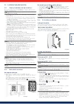
2 Connect the connectors
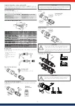
2.1 Connect the cable (Figure 35)
• Strip 15 mm of the cable with a suitable tool. Take care not to cut off any of the
individual wires.
1 Carefully insert the stripped cable with twisted wires as far as it will go.
The ends of the wires must be visible in the spring.
2 Close the spring. Make sure that the spring has engaged.
3 Push the insert into the sleeve.
4 Tighten the cable gland applying 2 Nm of torque.
2.2 Mate the connectors
• Connect the plug and socket to each other. The connection engages.
• Pull on the coupling to check there is a proper connection.
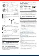
3 Disconnect the connectors (Figure 36)
You need a flat head screwdriver with a blade width of 3 mm (e.g., SZF 1-0,6x3,5,
1204517).
1 Insert the screwdriver as shown in Figure 36.
2 Leave the screwdriver in place and disconnect the socket and plug.
3.1 Disconnect the cable (Figure 37)
1 Unscrew the cable gland.
2 Insert the screwdriver as shown in Figure 37.
3 Lever the connection open and pull the sleeve and insert apart.
4 Open the spring with the screwdriver. Remove the cable.
Figure 35
Figure 37
Figure 36
Technical data as per standard
EN 50521
UL SUBJECT 6703
Ambient temperature
-40°C...+85 °C
-40°C...+70 °C
Rated voltage, max.
1100 VDC
600 VDC
Rated current, max.
2.5 mm
2
- 27 A; 4 mm
2
- 40
A; 6 mm
2
- 40 A
AWG 14 - 15 A, AWG 12 -
20 A, AWG 10 - 30 A
Cable diameter
5 ... 8 mm
5 ... 8 mm

