background image

2

EN

G

LI

SH

1.  General Safety Advice

Please ensure all necessary measures are taken to prevent accidents. The use of 

PowerSets in applications that may endanger human lives is prohibited, including 

in air and road transport systems.  

PowerSets must not be used for anything other than their expressed purpose.  

Solar Frontier strongly advises you to follow the instructions below in order to 

avoid bodily injury, damage to property and/or death.

PowerSets sold by Solar Frontier GmbH may only be installed by authorized 

professionals (see 4.2). As soon as it becomes evident that safe operation is 

no longer possible (e.g., visible damage), remove the PowerSet immediately 

from the grid.

1.1  Safety advice for Solar Frontier SF165-S/SF170-S 

photovoltaic modules


Installation, wiring and maintenance of SF modules must only be carried out 

by licensed and trained persons.


Ensure that all instructions and warnings related to SF modules and all instruc-

tions from the manufacturer of the system components are fully understood 

prior to installing and operating a PV solar system.


The front surface of SF modules should be covered with an opaque material 

during installation to decrease the potential of electrical shock.


SF modules only generate direct current (DC) electricity.


SF modules do not have the ability to store electricity.


SF modules will experience higher voltage when connected in series and 

higher electrical current when connected in parallel.


Only interconnect SF modules with similar electrical characteristics in series or 

in parallel to prevent system imbalance conditions and module damage. 


The PV array open circuit voltage must never exceed the maximum system voltage 

(including in low temperature conditions).


Excessive leakage currents are a shock and fire hazard.


Under no circumstances disconnect the cable from operational modules or 

electrical arcing may occur. This may result in serious bodily harm or death.


Do not use SF modules for purposes other than terrestrial power generation to 

prevent electrical shock, fire and other accidents. 


Do not artificially concentrate sunlight on modules using lenses or mirrors. 


Do not use light sources other than natural sunlight and general illumination for 

power generation.


Do not use SF modules in water or liquid. Contact with water or other liquid signifi-

cantly increases the risk of electric shock.


The level of leakage current must be limited in accordance with local regula-

tions for safety reasons.


Carefully check the polarity of the connections before installing. Incorrect wir-

ing may damage SF modules or appliances.


Only use tools, plugs, cables and support structures suitable for solar electric 

systems.


Wear appropriate protective clothing when working on SF modules and take 

all necessary precautions to prevent electric shock, especially when DC voltage 

exceeds 30 V. 

1.2  Safety advice for Turbo inverters


Install and use the device only after reading and understanding this document.


Always perform the measures described in this document in the sequence 

specified.


Keep this document in a safe place for the entire service life of the device. Pass the 

document on to subsequent owners and operators of the device.


Improper operation can reduce the yields of the photovoltaic system.


The device must not be connected to the DC or AC cables if it has a damaged 

casing.


Switch the device off immediately and disconnect it from the grid and the 

solar modules if any of the following components is damaged: 

- Device (not functioning, visible damage, smoke emission, penetration by  

  liquid, etc.) 

- Cables 

- Solar modules


The system must not be switched back on until 

- the device has been repaired by the dealer or manufacturer. 

- damaged cables or solar modules have been repaired by a technical  

  professional.


Never cover the Device.


Do not open the casing. Danger! This will void the warranty!


Factory labels and markings must never be altered, removed or rendered 

unreadable.


Observe the respective manufacturer‘s manual when connecting an external 

device that is not described in this document (e.g., external data logger). Incor-

rectly connected components can damage the inverter.

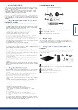
Safety advice for the device:

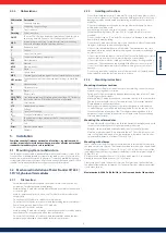
Figure 1

2

3

1

1

1

 Dangerous voltages can remain present on the components up to 10 minutes 

after switching off the DC circuit breaker 

and

 the line circuit breaker.

2

 Read and follow the instructions!

3

 Serial number as a bar code and in plain text

2.  Proper usage

The PowerSet may only be used in grid-connected photovoltaic systems. The 

modules, inverter, cables, and connectors have been mutually calibrated for best 

performance. The connections may not be grounded.

3.  Components included and structure of the 

PowerSet

The Solar Frontier PowerSet comprises the following components. The number of 

components required can be determined using the list below based on the type 

of PowerSet you have: 

1  

Solar Frontier SF165-S/SF170-S photovoltaic module

2  

Solar Frontier Turbo 1P Mini / 1P / 3P1 / 3P2 inverter (incl. inverter, mounting   
plate, 1 pair SunClix connectors and AC plug)

3  

Y-cables, Version for (+) and (-)

4  

DC plugs and DC sockets (3 of each in one pack) 

5  

Installation and maintenance manual


Summary of Contents for PowerSet 2.0-170-1p

Page 1: ...ation and Operating Manual PowerSet Turboand PowerSet Mini Installations und Bedienungsanleitung PowerSet Turbo und PowerSet Mini Manuale di installazione e funzionamento PowerSet Turbo e PowerSet Min...

Page 2: ...ion cable for connecting an energy meter 9 5 4 8 Connecting the inverter and switching on the AC power 9 5 4 9 Initial commissioning of the inverter 9 5 4 10 Switching on the DC supply 11 5 4 11 Feed...

Page 3: ...ly check the polarity of the connections before installing Incorrect wir ing may damage SF modules or appliances Only use tools plugs cables and support structures suitable for solar electric systems...

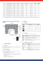
Page 4: ...matic structure based on PowerSet Turbo 3 1 example Inverter DC Cable with plug and socket Y Cable PV Generator Figure 2 4 About this Manual 4 1 Contents These instructions contain all information req...

Page 5: ...isuse of SF modules Do not drill additional mounting holes into the aluminium frame Only pre drilled holes should be used Avoid placing any stress onto the SF modules cables or connectors Minimum bend...

Page 6: ...mm 8 mm 3 mm 3 mm 10 0 29 0 31 in 0 31 in 0 12 in 0 12 in Figure 4 Module parallel to support rails 256 mm 75 mm 745 mm 75 mm 2 95 in 75 mm 75 mm 2 95 in 75 mm 2 95 in 75 mm 75 mm 2 95 in 75 mm 75 mm...

Page 7: ...bles must not be altered Please ensure a clean and proper assembly of the cables to avoid error sources and to ensure safe cabling The DC cables used must comply with the requirements specified in Sec...

Page 8: ...ss section of at least 2 mm AWG14 and a temperature range of at least 40 to 85 C Alternatively it is possible to use grounding lugs with integrated grounding pin lock washers and grounding clips or br...

Page 9: ...w the mounting plate to the mounting surface using 4 screws Use screws and dowels etc appropriate for the weight of the inverter The mounting plate must lie flat on the mounting surface and the metal...

Page 10: ...bed for the selected country Setting the country The following applies when setting the country The set country must always be the same as the country where the inverter is installed This causes the i...

Page 11: ...h 6 Press The year is selected 7 Repeat steps 1 to 3 for the year 8 Press ESC The check list is shown Time format 1 Press to select a time format 2 Press SET The time format is adopted 3 Press ESC The...

Page 12: ...to position 0 Figure 29 Figure 29 Finish Finish has been selected in the check list and SET has been pressed One of 2 possible dialogues is displayed 1 Proceed as follows depending on the dialogue Di...

Page 13: ...ches 2 Release the retaining plate 3 Lift the inverter with both hands until the hooks on the rear side of the inverter are free 3 4 Remove the inverter from the mounting surface 4 3 1 2 4 Figure 30 6...

Page 14: ...Meas values Reset max vals DHCP IP address Language Clear event log Submenus Information DNS Web portal Subnet mask Gateway Voltage limits off PowerStorage Energy meter RS485 address Dyn feedin contro...

Page 15: ...layed Press ESC The event message is confirmed Displaying event messages 1 Select Event log in the main menu 2 Press SET The event messages are displayed in chronological order latest message first 3...

Page 16: ...our installer Fan faulty The internal fan of the inverter is faulty In certain situ ations the inverter will feed less power into the grid Contact your installer Event message Description Type Grid fr...

Page 17: ...wer Sets A dry room should be chosen for storage The packaging is not waterproof All electronic components should be kept away from liquids during transport and stor age The SF PowerSets must remain i...

Page 18: ...module 2 400 Pa IEC61646 1 600 Pa design load UL1703 Module drawing 30 12 35 13 5 35 30 35 0 5 427 1 5 449 9 5 23 8 1257 2 977 2 90 444 20 565 5 5 574 9 5 7 0 5 934 2 598 5 5 1200 100 Grounding 474 9...

Page 19: ...00 VA 6200 VA Maximum active power cos 0 9 3600 W 5580 W Maximum apparent power cos 0 9 4000 VA 6200 VA Rated output 2000 W 4200 W 4000 W 6200 W Rated frequency 50 Hz and 60 Hz Grid type L N PE protec...

Page 20: ...kets Connection to PowerStorage 1 x RJ10 socket Connection to Modbus RTU meter ethernet interface for PowerMonitoring 1 x RJ45 Feed inmanagementasperEEG2012 EinsMan Ready via RS485 interface Integrate...

Page 21: ...15 0 0 20 15 0 40 10 600 15 0 4 50 0 5 0 1 0 5 0 1 no Italy 9 3908 Italia 9 8 300 230 15 0 0 20 15 0 40 10 600 15 0 4 50 0 5 0 1 0 5 0 1 yes Italy 10 3908 Italia 10 7 300 230 15 0 0 20 15 0 40 10 600...

Page 22: ...ndia 300 400 35 0 0 05 50 0 10 10 2 0 15 2 0 50 1 0 0 2 1 0 0 2 Italy 3 3902 Italia 3 30 400 22 0 0 10 25 0 20 50 5 0 0 2 5 0 0 2 Malaysia 6000 Malaysia 180 400 17 4 2 00 13 2 00 50 5 0 2 0 5 0 2 0 Ma...

Page 23: ...Weight ca kg km 38 4 57 6 Structure Tin plated copper strand fine wire as per IEC 60228 class 5 Polyolefin Double isolated Insulation chemically cross linked special compound 10 5 3 Product informati...

Page 24: ...ne stranded 4 0 also Flexible with ferrule 1 5 2 5 Screwless terminal Single stranded 1 5 2 5 also Flexible with ultrasound sealed conductor ends 1 5 2 5 also Flexible with ferrule 1 5 Crimp connectio...

Page 25: ...tive 94 9 EC ATEX 95 Appendix I the RST 20i2 i3 installation connectors are also devices in Device Group II Category 3D which according to Directive 99 92 EG ATEX 137 may be used in Zone 22 of combust...

Page 26: ...r no 05 502 2100 0 Bending radii Please comply with the minimum bending radius of the conductor Avoid traction on the contacts by 1 Bending the conductor as required 2 Cutting the conductor to length...

Page 27: ...issible ATTENTION Keep the connectors away from moisture and dirt Do not submerge the connectors in water Do not install the plugs directly on the roof cladding Fit connectors which are not connected...

Page 28: ...Systems 35 5 4 7 Modbus RTU Datenverbindungskabel f r den Anschluss eines Energiez hlers 35 5 4 8 Wechselrichter anschlie en und AC einschalten 35 5 4 9 Erste Inbetriebnahme des Wechselrichters 35 5 4...

Page 29: ...welche von den rtlichen Beh rden vorgegeben ist berpr fen Sie die Polarit t der Anschl sse vor der Installation sorgf ltig Fal sche Verkabelung kann die SF Module oder die Verbraucher besch digen Benu...

Page 30: ...iese Anleitung enth lt alle Informationen die eine Fachkraft zum Einrichten und zum Betreiben des PowerSets ben tigt Beachten Sie bei der Montage weiterer Komponenten z B AC Kabel Montagesys tem die A...

Page 31: ...e vorhandenen Bohrungen d rfen verwendet werden Vermeiden Sie mechanische Spannung an den Modulen Kabeln oder An schlussdosen F r die Modulkabel wird ein Kr mmungsradius von mindestens 39 mm empfohlen...

Page 32: ...m 75 mm Abbildung 4 Modul parallel zu den Montageschienen Querformat waagerecht Hochformat senkrecht 256 mm 75 mm 745 mm 75 mm 75 mm 75 mm 75 mm 75 mm 75 mm 75 mm 75 mm 75 mm 75 mm 75 mm 745 mm 256 mm...

Page 33: ...nd ordnungsgem e Konfektionierung der Kabel um m gliche Fehlerquellen auszuschlie en und um eine sichere Verkabelung zu gew hrleisten Die eingesetzten DC Kabel m ssen die im Abschnitt 10 5 2 definiert...

Page 34: ...handen sein Benutzen Sie ein Erdungskabel aus Kupfer mit einem Querschnitt von mindestens 2 mm AWG14 sowie einemTemperaturbereich von min 40 bis 85 C Alternativ k nnen auch Erdungsklemmen mit integrie...

Page 35: ...fl che befestigen Dem Gewicht des Wechselrichters entsprechende Schrauben und D bel etc verwenden Die Montageplatte muss eben an der Montagefl che anliegen die seitlichen Blechstreifen m ssen nach vor...

Page 36: ...rgeschrieben Einstellen des Landes F r das Einstellen des Landes gilt Es wird das Land eingestellt in dem der Wechselrichter installiert ist Dadurch l dt der Wechselrichter die vorgegebenen Netzparame...

Page 37: ...bernommen 4 dr cken Der Monat ist markiert 5 Schritte 1 bis 3 f r den Monat wiederholen 6 dr cken Das Jahr ist markiert 7 Schritte 1 bis 3 f r das Jahr wiederholen 8 ESC dr cken Die Checkliste wird an...

Page 38: ...ternativ kann unter diesem Men punkt auch die Funktion PowerStorage beim Einsatz eines Solar Frontier Batteriesystems aktiviert werden Details hierzu entneh men Sie bitte dem PowerStorage Handbuch Hin...

Page 39: ...og mit Ja geht 1 Schritt vor Tabelle 1 DC Anschl sse vom Wechselrichter trennen DC Kabel gem Anleitung des Herstellers trennen Dazu ist ein spezielles Werkzeug erforderlich Warnung DC Kabel f hren Spa...

Page 40: ...e Ausgangs leistung aktueller Tagesertrag Netzstrom Netz frequenz PV Spannung PV Strom Betriebs stunden Innen temperatur Leistungs reduzierung Abs Maximal leistung Tagesmaximal ertrag Tagesmaximal lei...

Page 41: ...Ereignismeldung mit dem Vermerk NEW wird angezeigt ESC dr cken Die Ereignismeldung ist quittiert Ereignismeldungen anzeigen 1 Im Hauptmen Ereignisprotokoll w hlen 2 SET dr cken Die Ereignismeldungen w...

Page 42: ...ndigen Sie Ihren Installateur Ereignismeldung Beschreibung Typ L fter defekt Der interne L fter des Wechselrichters ist defekt Der Wechselrichter speist m glicherweise mit verminder ter Leistung ins N...

Page 43: ...d Lagerung Achten Sie auf alle Hinweise auf der Verpackung wenn Sie SF PowerSets lagern oder transportieren F r die Lagerung sollte ein trockener Raum gew hlt werden Die Verpackung ist nicht wasserdic...

Page 44: ...35 13 5 35 30 35 0 5 427 1 5 449 9 5 23 8 1257 2 977 2 90 444 20 565 5 5 574 9 5 7 0 5 934 2 598 5 5 1200 100 Grounding 474 9 5 88 1 66 47 8 21 5 21 5 120 538 5 150 50 31 1 225 372 5 31 1 225 372 5 4...

Page 45: ...stung cos 0 95 2100 VA 4200 VA 4000 VA 6200 VA Maximale Wirkleistung cos 0 9 3600 W 5580 W Maximale Scheinleistung cos 0 9 4000 VA 6200 VA Nennleistung 2000 W 4200 W 4000 W 6200 W Nennfrequenz 50 Hz u...

Page 46: ...e Anschluss an Modbus RTU Z hler Ethernetschnittstelle f r PowerMonitoring 1 x RJ45 Einspeise ManagementnachEEG2012 EinsMan ready ber RS485 Schnittstelle Integrierter DC Lasttrennschalter ja konform z...

Page 47: ...0 15 0 4 50 0 5 0 1 0 5 0 1 nein Italien 9 3908 Italia 9 8 300 230 15 0 0 20 15 0 40 10 600 15 0 4 50 0 5 0 1 0 5 0 1 ja Italien 10 3908 Italia 10 7 300 230 15 0 0 20 15 0 40 10 600 15 0 4 50 0 5 0 1...

Page 48: ...n 9100 India 300 400 35 0 0 05 50 0 10 10 2 0 15 2 0 50 1 0 0 2 1 0 0 2 Italien 3 3902 Italia 3 30 400 22 0 0 10 25 0 20 50 5 0 0 2 5 0 0 2 Malaysia 6000 Malaysia 180 400 17 4 2 00 13 2 00 50 5 0 2 0...

Page 49: ...t ca kg km 38 4 57 6 Aufbau Cu Litze verzinnt feindrahtig nach IEC 60228 Klasse 5 Polyolefin Doppelt isoliert Isolation Au enmantel vernetztes Spezialcompound 10 5 3 Produktinformationen Y Kabel Herst...

Page 50: ...h flexibel mit Aderendh lse 1 5 2 5 Schraubenlose Klemmstelle eindr htig 1 5 2 5 zus tzlich flexibel mit ultraschallverdich teten Leiterenden 1 5 2 5 zus tzlich flexibel mit Aderendh lse 1 5 Crimpansc...

Page 51: ...G ATEX 95 An hang I auch Ger te der Ger tegruppe II Kategorie 3D die nach RL 99 92 EG ATEX 137 in der Zone 22 von brennbaren St uben eingesetzt werden d rfen Bei der Verwendung Installation sind die A...

Page 52: ...0 0 Biegeradien Beachten Sie den minimalen Biegeradius der Leiter Vermeiden Sie Zugkr fte auf die Kontaktstellen indem Sie wie folgt vorgehen 1 Leitung wie ben tigt biegen 2 Leitung abl nge 3 Abmantel...

Page 53: ...die Steckverbinder nicht unter Wasser Verlegen Sie die Stecker nicht direkt auf der Dachhaut Versehen Sie die Steckverbinder die nicht gesteckt sind mit einer Schutzkappe z B PV C PROTECTION CAP 1785...

Page 54: ...i collegamento dati RTU Modbus per collegare un contatore di energia 61 5 4 8 Collegamento dell inverter e accensione del lato CA 61 5 4 9 Prima messa in funzione dell inverter 61 5 4 10 Accensione de...

Page 55: ...i e supporti di montaggio compa tibili con sistemi elettrici solari Durante i lavori su moduli SF e specialmente quando il voltaggio CC supera i 30 V indossare indumenti protettivi idonei Usare esclus...

Page 56: ...stinatari Salvo diversamente indicato il presente manuale destinato solo a personale qualificato e al gestore dell impianto Nel presente manuale con il termine personale qualificato s intendono person...

Page 57: ...aggio addizionali nel telaio di alluminio Devono essere utilizzati esclusivamente i fori gi disponibili Evitare stress meccanici sui moduli FV SF cavi e connettori nel piegare i cavi si raccomanda un...

Page 58: ...clamp sul modulo minimo 8 mm 75 mm Figura 4 Modulo parallelo ai binari di montaggio Paesaggio orizzontale Ritratto verticale 256 mm 75 mm 745 mm 75 mm 75 mm 75 mm 75 mm 75 mm 75 mm 75 mm 75 mm 75 mm 7...

Page 59: ...non possono essere modificati Garantire un assemblaggio pulito e ordinato al fine di evitare errori e con nettere il tutto in modo sicuro I cavi DC impiegati devono soddisfare i requisiti di sezione d...

Page 60: ...terra usare filo di rame di diametro non inferiore a 2 mm 14AWG Il rating di temperatura dei conduttori deve essere da 40 a 85 C Come alternativa possono essere utilizzati per la messa a terra clips c...

Page 61: ...erficie di montaggio con 4 viti Utilizzare viti e tasselli ecc adatti al peso dell inverter La piastra di montaggio deve essere appoggiata in piano alla superficie di mon taggio le strisce di lamiera...

Page 62: ...caratteristica della potenza reattiva se prescritto per il Paese selezionato Impostazione del Paese Per l impostazione del Paese vale quanto segue Deve essere impostato l effettivo Paese di installazi...

Page 63: ...list Data 1 Premere SET Il giorno lampeggia 2 premere per modificare il giorno 3 Premere SET La modifica viene salvata 4 premere Il mese evidenziato 5 Ripetere i passaggi da 1 a 3 per il mese 6 premer...

Page 64: ...modificare il valore 4 Premere SET La modifica viene salvata 5 Se necessario ripetere i passaggi da 1 a 4 per gli altri parametri 6 Premere ESC Viene visualizzata la checklist Visualizzare linea carat...

Page 65: ...3 Sollevare l inverter con entrambe le mani fino a liberare i ganci sul retro dell in verter 3 4 Rimuovere l inverter dalla superficie di montaggio 4 3 1 2 4 Figura 30 6 Struttura e funzioni del Turb...

Page 66: ...di uscita Rend giorn att Sottomenu Informazione DNS Portale web Maschera di sottorete Gateway da PowerStorage Contatore di energia Indirizzo RS485 Limitazione dinamica Modo Risparmio di CO2 Rendiment...

Page 67: ...messaggi evento vengono visualizzati in ordine cronologico cominciando dal pi recente 3 Premere per scorrere l elenco dei messaggi evento Come richiamare e comandare il menu assistenza 1 Richiamare la...

Page 68: ...Guasto ventola Il ventilatore interno dell inverter guasto possi bile che l inverter immetta in rete con una potenza ridotta Informare l installatore Frequenza di rete troppo elevata per la riconness...

Page 69: ...Premere SET per confermare il risultato dell autotest Compare l indicatore di stato Messaggi degli errori che impediscono l autotest Messaggio Descrizione Rimedio Rilevato un errore Non stato possibi...

Page 70: ...e a circuito aperto Voc 100 V 102 V Corrente di corto circuito Isc 1 76 A 1 76 A Tensione nominale Vmpp 80 2 V 82 1 V Corrente nominale Impp 1 53 A 1 55 A 1 Informazioni misurate in condizioni di test...

Page 71: ...ssima cos 0 95 2100 VA 4200 VA 4000 VA 6200 VA Potenza attiva massima cos 0 9 3600 W 5580 W Potenza apparente massima cos 0 9 4000 VA 6200 VA Potenza nominale 2000 W 4200 W 4000 W 6200 W Frequenza nom...

Page 72: ...ntatore RTU Modbus Interfaccia Ethernet per PowerMonitoring n 1 RJ45 Gestione dell immissione secondo la legge tedesca sulle energie rinnovabili EEG 2012 EinsMan ready attraverso interfaccia RS485 Int...

Page 73: ...230 22 0 0 10 25 0 20 50 5 0 0 2 5 0 0 2 no Italia 8 3907 Italia 8 7 300 230 15 0 0 20 15 0 40 10 600 15 0 4 50 0 5 0 1 0 5 0 1 no Italia 9 3908 Italia 9 8 300 230 15 0 0 20 15 0 40 10 600 15 0 4 50...

Page 74: ...35 0 0 05 50 0 10 10 2 0 15 2 0 50 1 0 0 2 1 0 0 2 Italia 3 3902 Italia 3 30 400 22 0 0 10 25 0 20 50 5 0 0 2 5 0 0 2 Malesia 6000 Malaysia 180 400 17 4 2 00 13 2 00 50 5 0 2 0 5 0 2 0 Mauritius 23000...

Page 75: ...6 Struttura Rame stagnato in fili sottili come da IEC 60228 classe 5 Polyolefin Doppio isolamento Isolamento guaina esterna reticolata speciale 10 5 3 Informazioni prodotto cavi a Y Produttore HIS Pro...

Page 76: ...in aggiunta flessibile con le estremit dei conduttori saldate ad ultrasuoni 1 5 2 5 in aggiunta Flessibile con manicotto terminale 1 5 Collegamento a crimpare flessibile con le estremit dei conduttori...

Page 77: ...i per l installazione RST 20i2 i3 secondo RL 94 9 EG Appendice ATEX 95 fanno parte anch essi del gruppo di apparecchi II ca tegoria 3D che secondo RL 99 92 EG ATEX 137 possono essere utilizzati nella...

Page 78: ...impatura N d ordine 05 502 2100 0 Raggi di curvatura Notare il raggio minimo di curvatura dei conduttori Evitare forze di trazione nei punti di contatto effettuando le seguenti operazioni 1 Piegare il...

Page 79: ...o comune permesso ATTENZIONE Proteggere i connettori da umidit e sporcizia Non immergere i connettori nell acqua Non posizionare il connettore direttamente sulla copertura del tetto Dotare i connettor...

Page 80: ...en PowerStorage systeem 87 5 4 7 Modbus RTU dataverbindingskabel voor het aansluiten van een energiemeter 87 5 4 8 Omvormer aansluiten en AC inschakelen 87 5 4 9 Eerste inbedrijfstelling van de omvorm...

Page 81: ...et overschrijden Controleer de polariteit van de aansluitingen voor het installeren zorgvuldig Een verkeerde bekabeling kan de SF modules of de verbruikers beschadigen Gebruik uitsluitend gereedschapp...

Page 82: ...ndleiding bevat alle informatie die een vakman nodig heeft voor het instellen en gebruiken van een PowerSet Volg bij de montage van de overige componenten bijv AC kabels montagesys teem de handleiding...

Page 83: ...odules ontstaan Boor geen extra gaten in het aluminium frame Alleen de aanwezige boringen mogen worden gebruikt Vermijd mechanische spanningen bij de modules kabels of aansluitdozen Voor de modulekabe...

Page 84: ...le en klemmen min 8 mm 75 mm Afbeelding 4 Module parallel aan de montagerails Liggend horizontaal Staand verticaal 256 mm 75 mm 745 mm 75 mm 75 mm 75 mm 75 mm 75 mm 75 mm 75 mm 75 mm 75 mm 75 mm 75 mm...

Page 85: ...n gewijzigd Zorg voor het schoon en correct op maat maken van de kabels zodat mogelijke foutoorzaken worden uitgesloten en een veilige bekabeling is gewaarborgd De gebruikte DC kabels moeten voldoen a...

Page 86: ...aardingskabel van koper met een doorsnede van minimaal 2 mm AWG14 evenals een temperatuurbereik van 40 tot 85 C Als alternatief kunnen ook aardingsklemmen met een ge ntegreerde aardpen tand veerringen...

Page 87: ...montagevlak bevestigen Gebruik schroeven en pluggen etc die passen bij het gewicht van de omvormer De montageplaat moet vlak aanliggen op het montagevlak de plaatstroken aan de zijkant moeten naar vo...

Page 88: ...voor het betreffende land Instellen van het land Voor het instellen van het land geldt Het land waar de omvormer is ge nstalleerd wordt ingesteld Daardoor laadt de omvormer de vooringestelde netparam...

Page 89: ...eno men 4 indrukken De maand is gemarkeerd 5 Stappen 1 tot en met 3 herhalen voor de maand 6 indrukken Het jaar is gemarkeerd 7 Stappen 1 tot en met 3 herhalen voor het jaar 8 ESC indrukken Dechecklis...

Page 90: ...teristiek weergeven 1 De eerder ingestelde blindvermogenkarakteris tiek wordt grafisch weergegeven voorbeeld in afb links 2 ESC indrukken De checklist wordt weerge geven Afsluiten In de checklist is A...

Page 91: ...eide handen optillen tot de haken aan de achterkant van de omvormer vrij zijn 3 4 Omvormer van het montagevlak verwijderen 4 3 1 2 4 Afbeelding 30 6 Opbouw en werking Turbo omvormer 6 1 Behuizing Afbe...

Page 92: ...ogen Huidige dag opbrengst Netstroom Net frequentie PV spanning PV stroom Bedrijfsuren Binnen temperatuur Vermogens reductie Abs maximaal vermogen Maximale dag opbrengst Maximaal dag vermogen Gebeurte...

Page 93: ...elwaarde heeft betrekking op de gemiddelde waarde van de spanning 6 5 Verhelpen van storingen Storingen worden door meldingen weergegeven zoals hierna beschreven Het display knippert rood Tabel 2 Lijs...

Page 94: ...rbin ding tussen de omvormer en de energiemeter resp PowerStorage systeem Neem contact op met uw installateur om de verbinding te laten controleren Tabel 2 Melding Beschrijving Type Dataoverdracht mis...

Page 95: ...ort en opslag Volg alle aanwijzingen op de verpakking als u de SF PowerSets opslaat of transpor teert Voor de opslag moet een droge ruimte worden gekozen De verpakking is niet waterdicht Alle elektris...

Page 96: ...letekening 30 12 35 13 5 35 30 35 0 5 427 1 5 449 9 5 23 8 1257 2 977 2 90 444 20 565 5 5 574 9 5 7 0 5 934 2 598 5 5 1200 100 Grounding 474 9 5 88 1 66 47 8 21 5 21 5 120 538 5 150 50 31 1 225 372 5...

Page 97: ...cos 0 95 2100 VA 4200 VA 4000 VA 6200 VA Maximaal effectief vermogen cos 0 9 3600 W 5580 W Maximaal blindvermogen cos 0 9 4000 VA 6200 VA Nominaal vermogen 2000 W 4200 W 4000 W 6200 W Nominale frequen...

Page 98: ...J10 bus Aansluiting aan Modbus RTU meter etherne tinterface voor PowerMonitoring 1 x RJ45 Voedingsmanagement volgens EEG 2012 EinsMan ready via RS485 interface Ge ntegreerde DC lastscheidingsschakelaa...

Page 99: ...0 5 0 0 2 5 0 0 2 neen Itali 8 3907 Italia 8 7 300 230 15 0 0 20 15 0 40 10 600 15 0 4 50 0 5 0 1 0 5 0 1 neen Itali 9 3908 Italia 9 8 300 230 15 0 0 20 15 0 40 10 600 15 0 4 50 0 5 0 1 0 5 0 1 ja Ita...

Page 100: ...ndia 9100 India 300 400 35 0 0 05 50 0 10 10 2 0 15 2 0 50 1 0 0 2 1 0 0 2 Itali 3 3902 Italia 3 30 400 22 0 0 10 25 0 20 50 5 0 0 2 5 0 0 2 Maleisi 6000 Malaysia 180 400 17 4 2 00 13 2 00 50 5 0 2 0...

Page 101: ...en vertind fijndraads volgens EN 60228 klasse 5 Polyolefin Dubbelge soleerd Isolatie buitenmantel uithardende speciaalcompound 10 5 3 Productinformatie Y kabel Fabrikant HIS Product HISkon Splitter Te...

Page 102: ...lzen 1 5 2 5 Schroefloos klempunt eendraads 1 5 2 5 extra flexibel met ultrasoon gecomprimeerde geleiderui teinden 1 5 2 5 extra flexibel met adereindhulzen 1 5 Krimpaansluiting flexibel met ultrasoon...

Page 103: ...lage I ook apparaten uit apparaatgroep II cate gorie 3D die volgens RL 99 92 EG ATEX 137 in zone 22 van brandbare stofsoorten worden toegepast Bij het gebruik installeren moet worden voldaan aan de ei...

Page 104: ...adii Houd rekening met de minimale buigradii van de geleiders Voorkom trekkrachten op de contactpunten door als volgt te werk te gaan 1 Leiding zoals gewenst buigen 2 Leiding inkorten 3 Mantel strippe...

Page 105: ...gestaan LET OP Bescherm de stekkerverbindingen tegen vochtigheid en vuil Dompel de stekkerverbindingen nooit onder in water Leg de stekkers niet direct op de dakbedekking Voorzie de stekkerverbindinge...

Page 106: ...105...

Page 107: ...106...

Page 108: ...r Americas Inc 2099 Gateway Place Suite 310 San Jose CA 95110 USA Tel 1 408 916 4150 Europe Solar Frontier Europe GmbH Bavariafilmplatz 8 82031 Gr nwald bei M nchen Germany Tel 49 89 92 86 142 0 Middl...

Reviews: