3
Area
PowerSet Description
Capacity
Modules
Inverters
Grid connection
Y- cables
Plugs &
sockets
Modules
in series
15.6 m²
PowerSet Mini 2.0-170-1p
2.04 kWp
12 x SF170-S
1 x Turbo 1P Mini
1ph
3 (+) & 3 (-)
3 + 3
3
18.2 m²
PowerSet Turbo 2.4-170-1p
2.38 kWp
14 x SF170-S
1 x Turbo 1P
1ph
1 (+) & 1 (-)
3 + 3
7
23.4 m²
PowerSet Turbo 3.0-165-1p
2.97 kWp
18 x SF165-S
1 x Turbo 1P
1ph
2 (+) & 2 (-)
3 + 3
6
23.4 m²
PowerSet Turbo 3.1-170-1p
3.06 kWp
18 x SF170-S
1 x Turbo 1P
1ph
2 (+) & 2 (-)
3 + 3
6
23.4 m²
PowerSet Turbo 3.1-170-3p
3.06 kWp
18 x SF170-S
1 x Turbo 3P1
3ph
2 (+) & 2 (-)
3 + 3
6
26.0 m²
PowerSet Turbo 3.4-170-1p
3.40 kWp
20 x SF170-S
1 x Turbo 1P
1ph
3 (+) & 3 (-)
3 + 3
5
27.3 m²
PowerSet Turbo 3.6-170-1p
3.57 kWp
21 x SF170-S
1 x Turbo 1P
1ph
2 (+) & 2 (-)
3 + 3
7
31.2 m²
PowerSet Turbo 4.0-165-1p
3.96 kWp
24 x SF165-S
1 x Turbo 1P
1ph
3 (+) & 3 (-)
3 + 3
6
31.2 m²
PowerSet Turbo 4.1-170-1p
4.08 kWp
24 x SF170-S
1 x Turbo 1P
1ph
3 (+) & 3 (-)
3 + 3
6
31.2 m²
PowerSet Turbo 4.1-170-3p
4.08 kWp
24 x SF170-S
1 x Turbo 3P1
3ph
3 (+) & 3 (-)
3 + 3
6
36.4 m²
PowerSet Turbo 4.8-170-1p
4.76 kWp
28 x SF170-S
1 x Turbo 1P
1ph
3 (+) & 3 (-)
3 + 3
7
39.0 m²
PowerSet Turbo 5.1-170-3p
5.10 kWp
30 x SF170-S
1 x Turbo 3P2
3ph
4 (+) & 4 (-)
6 + 6
6
45.5 m²
PowerSet Turbo 6.0-170-3p
5.95 kWp
35 x SF170-S
1 x Turbo 3P2
3ph
4 (+) & 4 (-)
6 + 6
7
54.6 m²
PowerSet Turbo 7.1-170-3p
7.14 kWp
42 x SF170-S
1 x Turbo 3P2
3ph
5 (+) & 5 (-)
6 + 6
7
62.4 m²
PowerSet Turbo 8.2-170-1p
8.16 kWp
48 x SF170-S
2 x Turbo 1P
1ph
6 (+) & 6 (-)
6 + 6
6
Accessories configured for the PowerSets are separately available from Solar Frontier: DC cables, mounting and fastening material, tools for assembly of the cables...
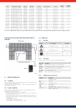
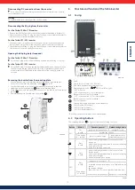
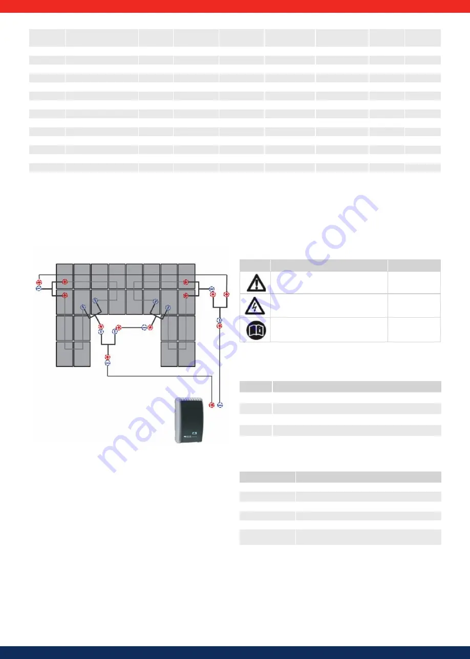
Schematic structure based on PowerSet Turbo 3.1
example
Inverter
DC-Cable with plug and socket
Y-
Cable
PV Generator
Figure 2
4. About this Manual
4.1 Contents
These instructions contain all information required by a technical professional for
setting up and operating the inverters.
When installing other components (e.g., AC cable, mounting system) follow the
manufacturer's instructions.
4.2 Target audience
Unless otherwise indicated, the target audiences of this manual are technical
professionals and system operators.
Technical professionals are persons who, for example:
•
have the knowledge of terminology and the skills necessary for setting up and
operating photovoltaic systems;
•
because of their professional training, knowledge and experience and knowl-
edge of the relevant regulations can assess the following tasks and recognise
possible dangers:
- mounting electrical devices
- assembling and connecting data cables
- assembling and connecting power supply cables.
4.3 Markings
4.3.1
Symbols
Symbol
Description
Location
General danger warning
Manual
Danger from electricity
Manual / device
Read manual before using the product.
Device
4.3.2
Keywords
Keywords used in conjunction with the symbols described above:
Keyword
Description
Danger
Immediate danger of death or serious bodily injury
Warning
Possible danger of death or serious bodily injury
Caution
Possible danger of light or medium bodily injury
Attention
Possible damage to property
Advice
Tips on operation or usage of the manual
4.3.3
Markings used in the text
Markings
Description
√
Condition for action
Single step
1., 2., 3., ...
Several steps in series
cursive
light emphasis
bold
strong emphasis
Courier
Designation of product elements such as buttons.,
displays, operating state

