4
EN
G
LI
SH
4.3.4
Abbreviations
Abbreviation Description
A
Current in amperes
AC
Alternating current voltage
DC
Direct current a
Derating
Power reduction
DHCP
The use of DHCP allows automatic integration of the device into
an existing network (Dynamic Host Configuration Protocol)
MSD
Internal mains monitoring for the inverter (mains monitoring
units with allocated all-pole switching devices).
RC
Residual current
I
Current
l
k
Short circuit current
I
mpp
Current at maximum power point
kVA
Kilovoltampere
kW
Kilowatt
kWh
Kilowatt-hour(s)
m
Metre
m
2
Square metre
MPP
Operating point with the highest output (maximum power point)
MPP tracker
Controls the power of the connected module strings to match the
MPP
Nm
Newton metre
P
Electrical power
Pa
Pascal
PV
Photovoltaic
SELV, TBTS,
MBTS
Schutzkleinspannung (EN: safety extra low voltage; FR: Très Basse
Tension de Sécurité; ES: Muy Baja Tensión de Seguridad)
SF
Solar Frontier
STC
Standard test conditions
U
Voltage
U
L
Open circuit voltage
U
mpp
Voltage at maximum power point
U
PV
The generator voltage present at the DC connection (photovol-
taic voltage)
V
Volt
W/m
2
Watt per square metre
η
Efficiency
5. Installation
Compliance with all relevant national and local laws, regulations and di-
rectives, especially for accident avoidance, as well as all relevant technical
standards is mandatory for a safe installation.
5.1 Mounting system / substructure
The PowerSets are delivered in standard form without an assembly system. Solar
Frontier offers a suitable assembly system as a separate accessory. For more infor-
mation, see: www.solar-frontier.eu. In general, all commonly available mounting
systems which ensure proper mounting following the guidelines in point 5.2.3 are
suitable. Your installer will be able to suggest an appropriate solution.
5.2 Mechanical installation of Solar Frontier SF165-S/
SF170-S photovoltaic modules
5.2.1
Site location
•
Ensure that the maximum wind and snow loads in local conditions do not
exceed the SF module maximum load ratings.
•
Avoid installing SF modules in areas where they are exposed to oil vapour and/
or corrosive gas.
•
Avoid accumulation of grit or dust on the SF modules as it may reduce the
output yield.
•
Do not expose SF modules to sulphurous atmospheres.
•
Do not install SF modules in locations where flammable gases accumulate or
flow as there is a risk of sparks from SF PV modules.
•
Do not install SF modules near fire.
•
Avoid installing SF modules in locations where they may be covered by perma-
nent shadows.This may adversely affect their performance.
•
Do not install SF modules in locations where temperatures exceed the tem-
perature range indicated in the module’s technical specifications.
5.2.2
Handling instructions
•
Do not disassemble or modify SF modules. This may result in an electric shock,
fire or other accidents. Solar Frontier cannot be held responsible for any loss or
damage caused by unauthorized disassembling, modification or misuse of SF
modules.
•
Do not drill additional mounting holes into the aluminium frame. Only pre-
drilled holes should be used.
•
Avoid placing any stress onto the SF modules, cables or connectors.
(Minimum bending radius of 39 mm (1.54 in) for module cables is recom-
mended)
•
Do not stand or step on SF modules. This may result in damage to the module
and/or bodily harm by falling.
•
Do not drop SF modules or drop objects onto them. Both sides of the module
(the glass surface and the back sheet) are fragile.
•
Do not strike the terminal box or pull the cables. The terminal box can crack
and break, while the output cable may unplug and cause electricity leakage or
an electric shock.
•
Do not scratch the back sheet or cables of the SF modules. Rubbing or scratch-
ing may result in an electric shock, electric leakage or an accident.
•
Do not scratch the insulation coating of the frame (except for the grounding
connection). This may weaken the strength of the frame or cause corrosion.
•
Do not cover the water drain holes of the frame. Doing so may cause frost
damage.
•
Do not use glue when closing the cover of the junction box. Similarly, do not
use a sealant to bond the junction box lid to its base.
5.2.3
Mounting instructions
Mounting structures cautions
• Pay attention to the electrochemical series when selecting support structure
material to avoid galvanic corrosion.
• Fasten and lock bolts completely. Inadequate mounting may result in SF mod-
ules falling or other accidents.
• Make sure that SF modules have been connected securely to the substructure.
The substructure should consist of durable, rustproof. UV resistant material.
Please adhere to national regulations.
• Ensure that your mounting support structure is designed to withstand the
SF module design snow and wind loads applicable for the chosen site. Solar
Frontier will not be responsible if the SF modules are damaged due to the
durability of the mounting support structure. Please consult your mounting
structure manufacturer.
Mounting the solar modules
• PV modules should typically face south in the Northern Hemisphere and north
in the Southern Hemisphere for optimum power production.
• Modules can be installed horizontally (landscape) or vertically (portrait).
• Maintain a space between SF modules and the roof. This will allow air to circu-
late, cooling the module, and allow condensation to dissipate. Solar Frontier
recommends a distance of at least 100 mm (3.94 in).
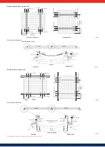
Mounting with clamps
Four or more corrosion-proof clamps should be used to fasten the SF modules to
the support structure securely. The clamps should be secured within the indicated
clamping zones (256 mm +/- 75 mm (10.08 in +/- 2.95 in) from the corners of the
long side of the module) using stainless steel M8 bolts with a minimum length of
20 mm (0.79 in).
All clamps must be at least 30 mm (1.18 in) long and 3 mm (0.12 in) thick and
overlap the module frame by 8 mm (0.31 in) or more.
Clamps must not create shadow nor cover the front glass, and shall not deform
the module frames during installation. For further instructions please contact the
clamp manufacturer.
Maximum load: 2.400 Pa (50 lbs/ft2) to the front and back of the module

