8
EN
G
LI
SH
5.4 Installation of Turbo inverters
5.4.1
Safety measures during installation
Observe the following safety notes when performing the work described in sec-
tion
Installation
.
Danger
Risk of death by electrocution
• Only technical professionals may perform the work described in section Instal-
lation.
•
Always disconnect all DC and AC cables as follows before starting work on the inverter:
1. Turn the AC circuit breaker to off. Take measures to prevent the system from
being unintentionally switched on again.
2. Set the DC circuit breaker on the inverter to position 0. Take measures to
prevent the system from being unintentionally switched on again.
3. Disconnect the Hosiden connectors of the DC cables according to
the manufacturer's instructions. A special tool is required for this.
Warning: DC cables are under current if light falls on the modules.
4. Remove the AC plug from the inverter as described in section 5.4.13.
5. Check that all pins of the AC plug are free of voltage. Use a suitable voltmeter
for this (do not use a simple neon phase checker).
•
Do not connect cables to the inverter until explicitly asked to do so in the
instructions.
•
Do not open the casing of the inverter.
•
Connect only SELV circuits to the RJ45 sockets.
•
Lay the cables such that the connection cannot come loose accidentally.
•
When laying cables, ensure that no damage occurs to any of the constructional
fire safety measures in the building.
•
Make sure that no flammable gases are present.
•
Observe all applicable installation regulations and standards, national laws and
connection values specified by the regional power supply company.
Attention
Danger of damage to the inverter or derating!
•
The mounting location must satisfy the following conditions:
- The mounting surface and the immediate environment are stationary,
vertical, level, flame retardant and not constantly vibrating.
- They meet the requirements for environmental conditions; see 10.2. Technical
data for Turbo inverter.
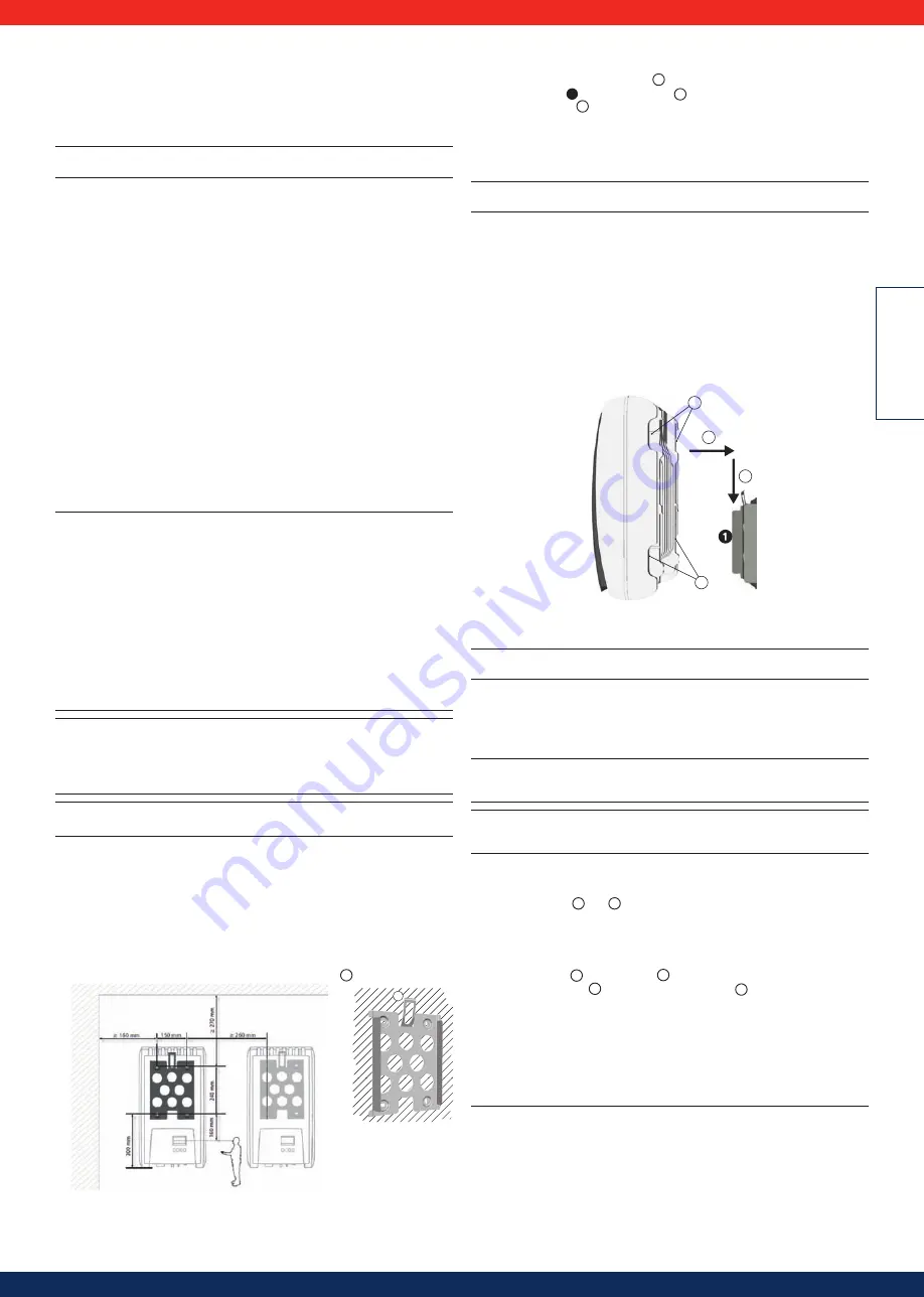
- The inverter has the following clearances around it:
above/below: at least 200 mm
to the sides/in front: at least 60 mm
•
Do not install the inverter in areas where animals are kept.
•
Observe the connection ratings specified on the type plate.
• The DC cables must not be connected to an earth potential (DC inputs and AC
output are not galvanically isolated).
Attention
When transmitting data over a public network:
•
Transmitting data over a public network can incur additional costs.
• Data transmitted over a public network is not protected from access by third
parties.
Advice
•
Avoid exposing the inverter to direct sunlight.
5.4.2
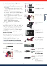
Mounting the inverter
Fastening the mounting plate
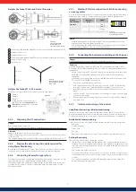
Screw the mounting plate to the mounting surface using 4 screws:
•
Use screws (and dowels etc.) appropriate for the weight of the inverter.
•
The mounting plate must lie flat on the mounting surface and the metal strips
at the sides must point forwards (Figure 22 ).
•
Install the mounting plate vertically with the retaining plate
1
at the top (Figure 22).
Figure 22
Figure 21
1
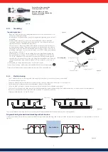
Mounting the inverter on the mounting plate
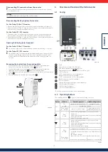
1. Pick up the inverter by its handles
1
or edges, place it in the middle of the
mounting plate
1
and press in gently
2
(Figure 23).
2. Lower the inverter
3
until the retaining plate on the mounting plate clicks
audibly into place.
The hooks on the back of the inverter must pass over the lugs on the mount-
ing plate.
3. The inverter must be firmly seated on the mounting plate and it must not be
possible to push it upwards.
Advice
The procedure for removing the inverter from the mounting plate is described in 6.4.9
5.4.3
Preparing the AC connections
Line circuit breaker
Information on the required line circuit breaker and the cables to be used between
the inverter and the line circuit breaker is provided in chapter 10.3.
Residual current circuit breaker
If the local installation regulations require the installation of an external residual
current circuit breaker, then a Type A residual current circuit breaker as per
IEC 62109-1, Section 7.3.8. is sufficient.
2
3
1
1
Figure 23
Wiring the AC plug
Danger
Risk of death by electrocution! Observe the warning notes in 5.4.1!
Grid voltage 220 V ... 240 V
Wire the AC plug supplied as described in 13.1.
Grid voltage 100 V ... 127 V
Danger
Risk of death by electrocution! Never connect one of the phases L1, L2 or L3 to PE
or N on the mains grid side.
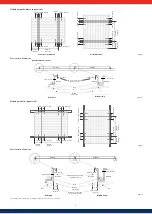
Advice
If the grid voltage is between 100 V and 127 V, the inverter can be connected
between the external conductors L1, L2 and L3 as follows:
2-phase mains grids
•
N and L are connected between the L1 – L2 external conductors on the
inverter side. See
2
and
3
in Figure 24.
•
One of the two connected external conductors is connected to PE at the
inverter side. This connection can be made within the AC plug or in an external
junction box.
•
Figure 24 shows an example of an inverter-side connection between L1 and PE:
Top: Connection
1
in the AC plug
5
Bottom: Connection
4
in an external junction box
6
3-phase mains grids
•
N and L are connected between the L1 – L2 or L1 – L3 or L2 – L3 external
conductors on the inverter side.
•
Connect the external conductor on the inverter side to PE: as above.
•
Figure 24: as above.
The external conductor voltages are shown in Figure 25.
1. Wire the AC plug supplied to match the selected external conductors, as
described in chapter 13.1. Do not yet close the AC plug.
2. Connect one of the two connected phases to PE at the inverter side. Make this
connection inside the AC plug or use an external junction box; see Figure 24.

