background image

Solar Venture 300W PV Array Operator and Maintenance Manual

October 2020

|


Contents

GENERAL INFORMATION, THEORY OF OPERATION, AND EQUIPMENT DESCRIPTION 

Introduction                                                                                                            4
Product Safety Information and Instructions                                                                       5

Safety Information Labels . . . . . . . . . . . . . . . . . . . . . . . . . . . . . . . . . . . . . . . . . . . . . 5
Fire Hazard  . . . . . . . . . . . . . . . . . . . . . . . . . . . . . . . . . . . . . . . . . . . . . . . . . . . . 6
Recommended Fire Extinguisher . . . . . . . . . . . . . . . . . . . . . . . . . . . . . . . . . . . . . . . . . 6
Electric Shock Hazard Related to PV Panels . . . . . . . . . . . . . . . . . . . . . . . . . . . . . . . . . . . 7

Environmental and Handling Precautions                                                                                                               8

Wind .   .   .   .   .   .   .   .   .   .   .   .   .   .   .   .   .   .   .   .   .   .   .   .   .   .   .   .   .   .   .   .   .   .   .   .   .   .   .   .   .   .   .   .   .   .   .   .   .   .   .   .   .   .   .   . 8
Water  . . . . . . . . . . . . . . . . . . . . . . . . . . . . . . . . . . . . . . . . . . . . . . . . . . . . . . . 8
Impact .   .   .   .   .   .   .   .   .   .   .   .   .   .   .   .   .   .   .   .   .   .   .   .   .   .   .   .   .   .   .   .   .   .   .   .   .   .   .   .   .   .   .   .   .   .   .   .   .   .   .   .   .   .   . 8
Dust . . . . . . . . . . . . . . . . . . . . . . . . . . . . . . . . . . . . . . . . . . . . . . . . . . . . . . . . 8
Heat . . . . . . . . . . . . . . . . . . . . . . . . . . . . . . . . . . . . . . . . . . . . . . . . . . . . . . . . 8

Theory of Operation                                                                                                   9
Equipment Description                                                                                             10

Kit Components .   .   .   .   .   .   .   .   .   .   .   .   .   .   .   .   .   .   .   .   .   .   .   .   .   .   .   .   .   .   .   .   .   .   .   .   .   .   .   .   .   .   .   .   .   .   .   .   . 10

OPERATOR INSTRUCTIONS

Solar Venture 300W PV Array Setup                                                                               11

Position and Orient System Components.   .   .   .   .   .   .   .   .   .   .   .   .   .   .   .   .   .   .   .   .   .   .   .   .   .   .   .   .   .   .   .   .   .   .   . 11
Deploy the PV Array Support Frame  . . . . . . . . . . . . . . . . . . . . . . . . . . . . . . . . . . . . . . 12
Install the Large Ground-securing Mesh  . . . . . . . . . . . . . . . . . . . . . . . . . . . . . . . . . . . . 13
Install the Small Ground-securing Mesh  . . . . . . . . . . . . . . . . . . . . . . . . . . . . . . . . . . . . 14
Install the PV Array on the Support Frame . . . . . . . . . . . . . . . . . . . . . . . . . . . . . . . . . . . 16
Connect the Solar Cable to the PV Panel Leads . . . . . . . . . . . . . . . . . . . . . . . . . . . . . . . . 17
Connect PV Array(s) to Solar Only Input Port of Power Hub . . . . . . . . . . . . . . . . . . . . . . . . . . 18

Position the PV Arrays for Optimal Power Generation                                                           19
Derating, Solar Loading, and Airflow                                                                                                                                                          19
Secure the Array to the Ground                                                                                                                                                                      20
Disassembling and Repacking the PV Array                                                                      21

MAINTENANCE

Preventive Care and Maintenance                                                                                 22
PV Array Conditional Maintenance                                                                                                                                                               22
Measuring PV Array Voltages: Background                                                                       22

Procedure to Measure PV Array V

oc 

with a Multimeter  . . . . . . . . . . . . . . . . . . . . . . . . . . . . . 23

SUPPORTING INFORMATION

Technical Specifications                                                                                            24

ABOUT SOLAR STIK, INC 

Contact                                                                                                               27

Summary of Contents for 19-1000010

Page 1: ...er 2020 OPERATOR AND MAINTENANCE MANUAL FOR THE SOLAR VENTURE 300W PHOTOVOLTAIC ARRAY P N 19 1000010 DISTRIBUTION STATEMENT A Approved for public release distribution is unlimited Updated 2020108 Version 1 0 ...

Page 2: ...n and Orient System Components 11 Deploy the PV Array Support Frame 12 Install the Large Ground securing Mesh 13 Install the Small Ground securing Mesh 14 Install the PV Array on the Support Frame 16 Connect the Solar Cable to the PV Panel Leads 17 Connect PV Array s to Solar Only Input Port of Power Hub 18 Position the PV Arrays for Optimal Power Generation 19 Derating Solar Loading and Airflow 1...

Page 3: ...tion 13 Figure 7 Small ground securing mesh installation 14 Figure 8 Ground securing mesh configuration for 30º array deployment 15 Figure 9 Ground securing mesh configuration for 60º array deployment 15 Figure 10 Connecting array hooks to support frame 16 Figure 11 Locking the array into place on the support frame 16 Figure 12 Connecting the PV array to the Solar Cable 17 Figure 13 PV arrays conn...

Page 4: ...S Peak shaving to decrease reliance on power from utility or grid The Solar Venture 300W PV Array is modular and scalable allowing users to tailor power generation capability to load requirements Setup requires no tools and the 300 W Array is Plug Play compatible with Hybrid Power Systems The mono crystalline cells in the high efficiency Venture Series panels are laminated onto a carbon fiber stru...

Page 5: ... hazardous situation which if not avoided will result in death or serious injury WARNING Indicates a hazardous situation which if not avoided could result in death or serious injury CAUTION Indicates a hazardous situation which if not avoided could result in minor or moderate injury All safety messages will identify what the potential hazard is how to reduce the chance of injury and what can happe...

Page 6: ...e is a liquefied gas which is highly effective fighting class B and C fires These extinguishers are ideal for areas where contamination and or cleanup are a concern such as data processing centers labs and telecommunication rooms Use Sweeping Motion WARNING Only CO2 carbon dioxide fire extinguishers should be used with this equipment Using the Fire Extinguisher When using the extinguisher on a fir...

Page 7: ...uld be taken to protect against electrocution Always work with another person in case an emergency occurs Disconnect power before checking controllers or performing maintenance Be sure the generator is properly grounded Wear safety glasses whenever working on any part of the System that requires exposure to mechanical or direct electrical contacts PV panels produce electricity when exposed to sunl...

Page 8: ...be protected from being struck by hard objects Dust This equipment is designed for operation in climates where high levels of dust or other particulates may exist Clean the surface of the PV panels regularly to maintain maximum output Dirty panels produce less power Heat Heat and solar loading reduce efficiency and life expectancy Shade products except PV panels to prevent the negative effects of ...

Page 9: ... Placing metal contacts on the top and bottom of a PV cell harnesses this current so it can power external appliances much like a traditional power generator On their own PV cells produce a limited amount of power but when arranged and electrically connected in a PV panel the power generated is directly related to how much cumulative current and voltage the PV cell arrangement is configured for Th...

Page 10: ...Venture 300W PV Array 1 Hard transport case 2 4 section foldable PV array 3 Ground securing mesh large and small 4 Support frame 5 Sandbags 12 ea 6 Solar Cable sold separately Figure 3 Solar Venture 300W PV Array components in transport case top and unpacked bottom 6 3 5 4 2 1 Equipment Description ...

Page 11: ...l Solar Cable provided is 30 long other lengths are available Figure 4 Working space radius for the PV arrays and associated equipment Solar Venture 300W PV Array Setup 30 PV arrays Power Management Energy Storage components The PV array can be deployed within a 30 radius the length of the Solar Cable of the component to which it will be connected If the PV array must be deployed more than 30 from...

Page 12: ...ransport strap securing the foldable array support frame Figure 5A Remove the two locking pins Figure 5B to allow the frame to expand Expand the support frame Figure 5C and install the locking pins in the deployed position Figure 5D after the support frame is fully extended Figure 5E Tensioning clamps Locking pins in deployed position Figure 5 Deploying the PV array support frame ...

Page 13: ...e Figure 6A The clips on the short side connect to the rings on the three 3 cleats Figure 6B of the support frame Connect the four 4 clips on the long side of the ground securing mesh to the wire loops Figure 6C at the low end of the support frame bar Figure 6D The mesh will be stretched tight when all of the connections are made A B C D Cleat rings Wire loop Figure 6 Large ground securing mesh in...

Page 14: ...nd securing Mesh The small ground securing mesh has three 3 clips on the short side and four 4 on the long side Figure 7A The clips on the short side connect to the rings Figure 7B on the three 3 cleats of the support frame Figure 7C Figure 7 Small ground securing mesh installation A B C Cleat rings ...

Page 15: ... for 30º array deployment Ground securing Mesh Configuration for Low and Steep angle Deployments Figure 9 Ground securing mesh configuration for 60º array deployment Connect the large and small ground securing meshes as shown in Figure 8 to deploy the PV array at 30º and as shown in Figure 9 to deploy the PV array at 60º ...

Page 16: ... hooks first and the top row of hooks second Figure 10B B Connect array to lower hooks first Connect array to upper hooks second The hooks on the upper row are part of a sliding tensioning clamp Unlock and lift the clamp lever to allow the hook to slide down Figure 11A Place the hook into the hole then tighten Figure 11B and lock the clamp Figure 11C Repeat for each of the four mounting holes unti...

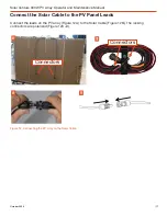
Page 17: ...nance Manual Connect the Solar Cable to the PV Panel Leads Connectors A B C D Connect the leads on the PV array Figure 12A to the Solar Cable Figure 12B The locking connectors are polarized Figure 12C D Figure 12 Connecting the PV array to the Solar Cable Connectors ...

Page 18: ...h to the Power Hub has been verified and the arrays have been oriented optimally toward the sun Connect the Solar Cable s to the Solar Only Input ports on the side of the Power Hub A maximum of six 6 PV arrays can be connected to the Power Hub PV arrays Power Hub Note This example describes connection to a Power Hub however other Solar Stik components such as the PRO Verter S Power Paks and BOS ha...

Page 19: ...n is higher overhead during the summer and lower on the horizon during the winter Power output of the PV arrays can be monitored in real time on the Power Hub User Interface See the Power Hub Operator Manual for instructions Monitoring the power output while orienting and choosing the best tilt angle for the panels will assist in finding and maintaining optimum power output throughout the year Pos...

Page 20: ...ult in PV array damage injury or death in high winds Wind damage can render arrays nonfunctional or significantly reduce their functional life expectancy PV arrays must be properly secured to the ground even in low wind environments Note Before the arrays are secured to the ground be observant and take care to ensure the support frame is not twisted If the support frame is twisted the array will b...

Page 21: ...e the PV array from the support stand Fold the PV array as shown in Figure 15 A Place the folded PV array into the transport case and cover it with the case foam Remove the locking pins deployed position from the PV array support frame collapse fold the support frame and return the locking pins to the storage position Fasten the transport strap Place the support frame into the transport case on to...

Page 22: ... one or more of the PV arrays may be under performing If a disparity in performance is observed during normal operation measure the voltage of each array independently using a handheld multimeter Figure 16 or the meters provided in the Power Hub User Interface Note The charging current from the PV arrays as reported by the Power Hub User Interface will be low even in full sun when the System batte...

Page 23: ...nd place the meter probes into the array lead connectors orange boxes in Figure 16 Under ideal conditions the reading should be 65 V If a normal voltage reading cannot be measured at pins A and B of the Solar Cable but CAN be measured at the PV array lead connectors replace the Solar Cable Contact Solar Stik if a PV array voltage measurement indicates that a PV array is either not functioning or i...

Page 24: ...nd workmanship Environmental Operating Temperature 40 to 194 F 40 to 90 C Storage Temperature 40 to 194 F 40 to 90 C Operating Humidity 0 to 95 RH up to 140 F 60 C Ingress Protection MIL STD 810 Method 512 Procedure I Immersion MIL STD 810 Method 510 Procedure I Blowing Dust Loose Cargo MIL STD 810 Method 514 Procedure II Transit Drop MIL STD 810 Method 516 Procedure IV Vibration MIL STD 810 Metho...

Page 25: ... Weight 23 6 lb 10 7 kg Transport Weight 45 6 lb 20 7 kg 53 1 lb 24 1 kg with 30 ft Solar Cable Solar Array Dimensions Assembled 65 x 43 x 0 2 in 165 x 109 x 0 5 cm Folded 16 x 43 x 1 5 in 41 x 109 x 3 8 cm Assembled Dimensions 65 x 48 x 4 in 165 x 122 x 10 cm Transport Dimensions Case external 49 7 x 21 5 x 8 87 in 126 x 54 6 x 22 5 cm Connections Solar Array Connectors MC4 ...

Page 26: ...Solar Venture 300W PV Array Operator and Maintenance Manual October 2020 26 ...

Page 27: ... of small scale renewable energy power generation systems with detailed explanation of system components Advanced configuration options with hands on deployment of actual systems will enhance student understanding Solar Stik New Equipment Training on site teaches Hybrid System configuration options with hands on deployment of actual systems to enhance student understanding Solar Stik Training Cour...

Reviews: