April 2021
|
Solar Stik
®
, Inc.
32
|
24VDC HyPR 3000 Operator and Maintenance Manual
PRELIMINARY DRAFT
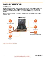
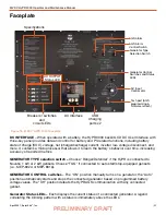
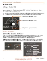
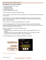
AC INPUT CONTROL dial
– Allows selection of AC input current limit. This must be adjusted to
match the maximum recommended current output limit of the AC power source. Recommended
settings are found on HyPR 3000 I-Plate.
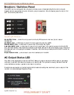
AC OUTPUT Status LED
– Green indicates the HyPR inverter is operating normally and AC power is
available from the 120 VAC output ports. A red LED indicates an inverter fault.
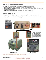
AGS ALARM CONTROL Switch –
The audible alarm indicates a connected generator is in the
process of starting. This alarm may be defeated (toggle switch) when silent operation is required.
USB CHARGING Ports
– The USB ports are for charging only; no data are transmitted via these
ports.
Breakers/Switches
– The breakers serve as switches to activate circuits and to deactivate circuits
not in use. Circuit breakers protect against overcurrent conditions in dedicated circuits. If too much
amperage flows due to short-circuit, inadequate or improper loading, or component failure, these will
protect the System and Operator. The green LED by each breaker will be lit if the circuit is active and
the breaker is not tripped.
AGS TECH PORT
– This port is used to program the Auto Generator Start/Stop module and
to update firmware if/when necessary. Please contact Solar Stik Technical Support for further
information.
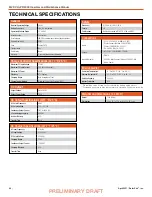
Specifications
– A list of performance metrics and limitations for the HyPR; provides guidance when
configuring a System.

