April 2021
|
Solar Stik
®
, Inc.
8
|
24VDC HyPR 3000 Operator and Maintenance Manual
PRELIMINARY DRAFT
General Information
Circuit breakers on faceplate are only for IN/OUT circuit limit protections. They are NOT “function
controls” or “function protections”.
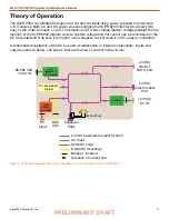
The internal DC Bus is limited to 100 A total current flow. This may restrict some HyPR functionality
in certain operating modes.
Current flow on the DC bus is controlled by voltage. Power will always be prioritized to the loads and
will only cease when the voltage drops to low-voltage disconnects located within the inverter (AC
loads), the ESMs and DC Interface (DC loads).
24 VDC IN/OUT NATO and 24VDC IN/OUT ports operate directly from the internal DC bus. Power
in/out of these ports will only be reflected in the “net” current in/out of the ESMs when a PV array is
connected.
System recovery from overdischarged batteries is possible using AC power or alternative 24 VDC
power sources. System recovery using PV power is not an option.
Inverter “continuous AC power output” fluctuates based on conditions such as temperature (heat
derating = efficiency loss).
AC Functions
The HyPR employs two (2) separate AC functions that operate on the DC bus:
Charging
AC>DC converter provides up to 100 A at 29 V DC to the DC bus (~3000 W).
Inverting
DC>AC inverter removes up to 84 A at 24 VDC from the internal DC bus (~2000 W).
When configuring the HyPR for use, it is important to understand how to establish balance between
the power available from sources and the power required by the loads.
When using AC power sources in Hybrid or UPS models, the AC INPUT setting must be set for the
following conditions:
• continuity of AC load operation
• battery charging
• not to exceed the power output of the AC source
When small expeditionary generators are used, the HyPR can be used for dynamic loads that would
normally cause overloading of the generator.


