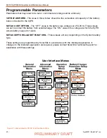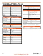
April 2021
|
Solar Stik
®
, Inc.
34
|
24VDC HyPR 3000 Operator and Maintenance Manual
PRELIMINARY DRAFT
AC Interface
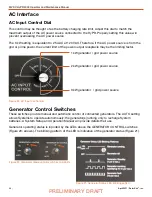
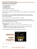
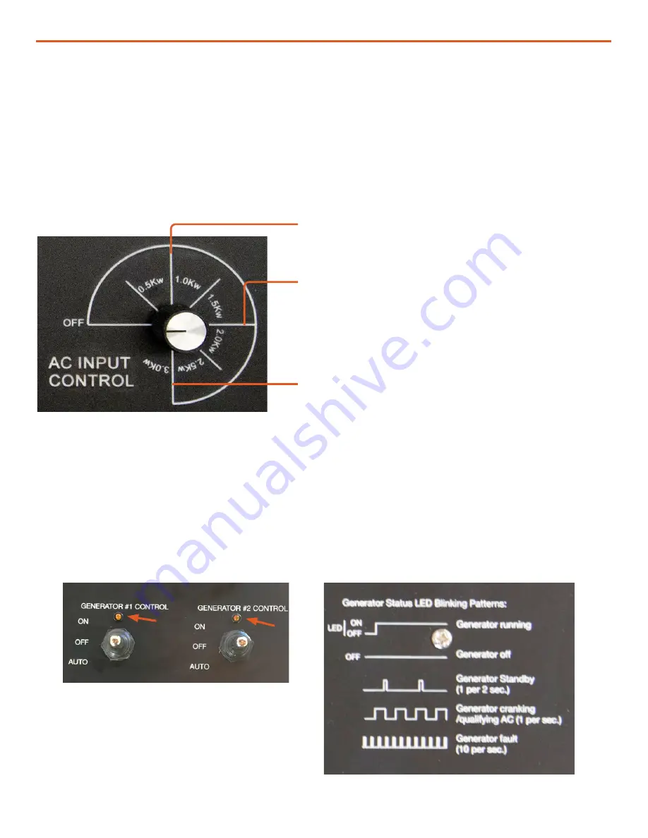
This control may be thought of as the battery charging rate limit. Adjust this dial to match the
maximum output of the AC power source connected to the HyPR. Properly setting this value will
prevent overloading the AC power source.
The 3 kW setting is equivalent to 25 AAC at 120 VAC. Therefore, if the AC power source is from the
grid or prime power, the current limit of the power output receptacle may be the limiting factor.
Figure 22. AC Input Control dial
1 kW generator / grid power source
2 kW generator / grid power source
3 kW generator / grid power source
Generator Control Switches
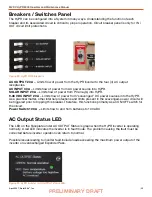
Figure 20. Generator mode control switches and LEDs
Figure 21. Generator Status LED blinking pattern
Generator operating status is reported by the LEDs above the GENERATOR CONTROL switches
(Figure 20; arrows). The blinking pattern of the LED is indicative of the generator status (Figure 21).
These switches provide manual and automatic control of connected generators. The AUTO setting
allows Systems to operate autonomously; the generator(s) running only to recharge System
batteries. A System Setup and Operation Manual will provide details their use.
AC Input Control Dial


