|
35
April 2021
|
Solar Stik
®
, Inc.
PRELIMINARY DRAFT
24VDC HyPR 3000 Operator and Maintenance Manual
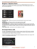
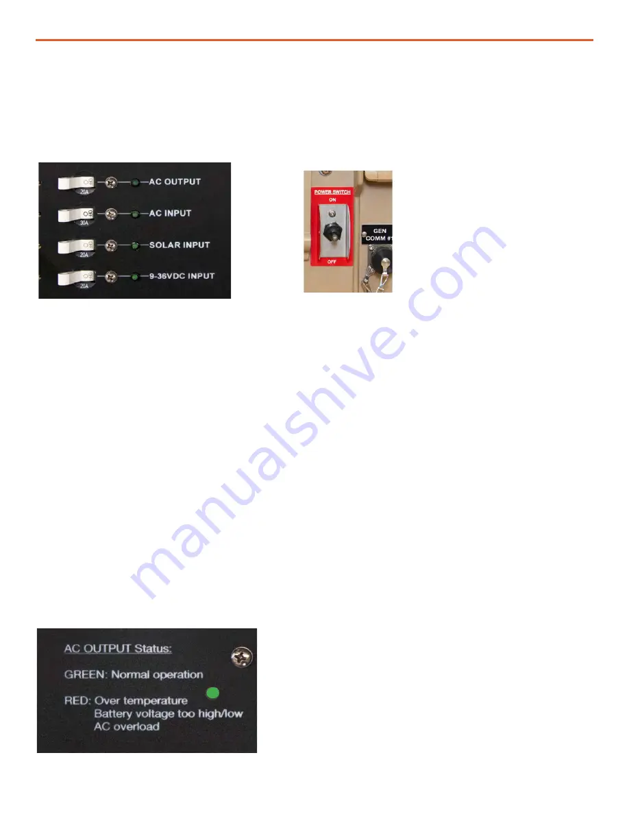
AC OUTPUT 20 A
– Limits flow of power from the HyPR inverter to the four (4) AC output
receptacles.
AC INPUT 30 A
– Limits flow of power from AC power source into HyPR.
SOLAR INPUT 20 A
– Limits flow of power from PV array(s) into HyPR.
9-36 VDC INPUT 20 A
– Limits flow of power from “scavenged” DC power sources into the HyPR.
As a practical matter, other internal protections and limits present in the scavenged-power circuit will
be triggered prior to tripping this breaker. Therefore, this functions primarily as an ON/OFF switch for
the circuit.
Power Switch 100 A –
Limits flow to and from batteries to 100 ADC.
Breakers / Switches Panel
Figure 23. HyPR 3000 breakers
The HyPR can be configured into a System in many ways. Understanding the function of each
breaker and its associated circuit is critical to proper operation. Circuit breaker panel is only for IN /
OUT circuit limit protections.
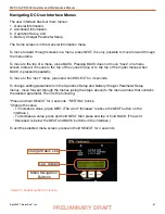
AC Output Status LED
The LED on the Faceplate under AC OUTPUT Status is green when the HyPR inverter is operating
normally. A red LED indicates the inverter is in fault mode. The problem causing the fault must be
corrected before inverter operation can return to normal.
Possible issues leading to inverter fault include loads exceeding the maximum power output of the
inverter or overdischarged Expander Paks.
Figure 24. HyPR Inverter / AC OUTPUT status LED


