background image


|

 27

October 2019 

24VDC Power Hub 2500 Operator Manual

Heat and Derating

The function and efficiency of all electronic equipment is related to and dependent upon the 
temperature at which it is operating. All equipment performs optimally within a narrow temperature 
range and less so as the temperature exceeds the upper end of that range. PV panel output drops 
off significantly in high heat as well. The Power Hub generates heat as a by-product of processing 
incoming PV power. Under normal circumstances, the amount of heat generated in this way will not 
exceed the rated temperature for the Power Hub to function at its rated capacity. 

Causes of Overheating  

The two (2) most common reasons for the Power Hub to overheat are high ambient temperature 
and solar loading (heat accumulation due to the sun shining directly the Power Hub). These two 
factors work together to elevate the internal operating temperature to the point where the solar 
chargers may automatically derate or even temporarily suspend output to prevent damage to 
their internal electronics. The solar chargers are rated to provide full power up to 104 ºF (40 ºC). 
Performance of the Power Hub will decline (charging current reduced) as the temperature increases 
or is sustained above this value.

Note:

 The charging current reported by the Power Hub battery monitor will also approach zero 

(0) A as the batteries approach a fully-charged state.

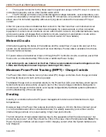
DEVICE LIST

Battery Monitor

Time

100% 0.0A

0.0W

Solar Charger #1

Solar Charger #2

Solar Charger #3

>

>

>

>

Battery Monitor

Battery

Time

26.33 V 0.0A

0.0W

State of charge

Temperature

Starter voltage

Consumed AmpHours

Time-to-go

Relay state

100%

0.01V

0.0Ah

--

Off

75 ºF

Figure 22. Power Hub internal temperature report on user interface

Power Hub Internal Cooling

Thermostat-controlled, internal cooling fans turn on at ~104 ºF (40 ºC) to maintain the internal 
temperature within the optimal operating range. The fans are audible when operating. Clogged 
air intake filters can significantly exacerbate heat-related problems, so they should be cleaned as 
often as necessary to maintain maximum airflow

Clean or replace the air filter

 monthly, or more 

frequently if operating in very dusty environments. Do not operate the Power Hub in direct sunlight 
or directly on the ground. It should be placed in a shaded, well-ventilated location. Proper air filter 
maintenance and shading the Power Hub will help to ensure that the internal temperature does not 
reach critical levels. 

Power Hub Internal Temperature Report

The Power Hub has a sensor that measures and reports the internal temperature. The internal 
temperature of the Power Hub (NOT the batteries) is reported in the Battery Monitor menu page. To 
access this and other battery-related data, press the Menu button to show the device list. Select/ 
highlight “Battery Monitor” and either right-click or press the Select button to display. 

Summary of Contents for 24VDC POWER HUB 2500

Page 1: ...OPERATOR MANUAL FOR 24VDC POWER HUB 2500 October 2019 DISTRIBUTION STATEMENT A Approved for public release distribution is unlimited Version 1 0 Updated 20191004 P N 20 0302207 2...

Page 2: ...ls 13 Derating 13 The Inter Connect System 14 Equipment Description 16 Connection Ports and Vents 16 Internal Cooling 18 Information Plate I Plate 18 Faceplate 19 OPERATOR INSTRUCTIONS Connections 20...

Page 3: ...Power Up 33 Performance Issues Causes and Solutions 33 Data Logging and Remote Monitoring 34 Performance and Troubleshooting 34 Data Storage and Retrieval 34 MicroSD Card Formatting 35 Remote Monitori...

Page 4: ...ection 21 Figure 15 Power Hub 24 VDC IN OUT ports 21 Figure 16 Power Hub Tech port 21 Figure 17 LCD user interface and navigation guide 22 Figure 18 Data views displayed in Pages 22 Figure 19 Device l...

Page 5: ...wer generation is required to support a battery Reducing generator run time in a hybrid system is critical Less reliance on grid utility power is desirable DC power management and distribution is requ...

Page 6: ...nts Consequently not every feature in the Power Hub may be used for an application The Power Hub can support operation with either lead acid or lithium battery types Other changes in programming may i...

Page 7: ...of the following Peak Shaving Inverter operation Battery charging Product Safety Information and Instructions This manual contains important safety instructions that must be followed during the instal...

Page 8: ...lert symbol and the word DANGER WARNING or CAUTION These words are defined as DANGER Indicates a hazardous situation which if not avoided will result in death or serious injury WARNING Indicates a haz...

Page 9: ...ansformers and appliances Remove the power source and the class C fire becomes a class A or B fire Recommended Fire Extinguisher NSN 4210 00 288 7219 Fire Extinguisher Carbon Dioxide 10 lb Carbon diox...

Page 10: ...cal shock DON T LET THIS BE YOU HIGH VOLTAGE System components PV arrays and generators may have lethal line voltages Extreme care should be taken to protect against electrocution Always work with ano...

Page 11: ...nly be open to access operator controls and closed at all other times Impact Equipment should not be dropped onto hard surfaces at a height greater than one foot when transporting or during operation...

Page 12: ...y State of Charge SoC The MPPT process allows a PV array to operate at its rated available voltage turning the higher PV voltage into charging current amps which is then provided to the battery at the...

Page 13: ...ontroller circuits as well as power that flows out to a connected battery PRO Verter or additional Power Hub s Only certain ports are metered on the Hub Follow recommended connection diagrams on the I...

Page 14: ...Connect Circuit use one value to successfully operate in concert battery voltage The Inter Connect Circuit communicates battery voltage to all components on the network allowing them to independently...

Page 15: ...place Rotate knob clockwise to lock counterclockwise to release Can be repaired or modified in the field connection within the circuit is minimized If a problem occurs in a leg of the Inter Connect C...

Page 16: ...ct connections between components Please review the information on all of these plates and labels as they contain the basic information required to set up and operate the Power Hub A May be connected...

Page 17: ...PV array input A B Description Connector Amps Voltage A 24 VDC NATO Slave unmetered NATO Slave 100 24 VDC B Regulated 24 VDC Input Only unmetered Inter Connect Port 100 total 24 VDC Figure 7 Right Si...

Page 18: ...Information All System components should be connected as described on the I Plate Warnings and Notices are provided Be familiar with their content before operating the Power Hub An I Plate is usually...

Page 19: ...PV Charging Specifications Ultra fast Maximum Power Point Tracking MPPT Maximum PV input voltage per connector 100 VDC Maximum solar input per connector 450 W Maximum output power 2500 W Maximum outpu...

Page 20: ...fely accepts up to 1250 watts of power from PV arrays or 450 watts max per input connector Different types of PV arrays can be connected to the Power Hub simultaneously as long as their specifications...

Page 21: ...cess to the data provided by it Figure 15 Power Hub 24 VDC IN OUT ports Powering up the Power Hub User Interface The user interface will activate when the Power Hub Inter Connect Circuit is active Pow...

Page 22: ...bank voltage Net current flowing to or from the System batteries Depending on how the System is configured the LCD shows capabilities that may or may not be utilized by the Power Hub so icons and win...

Page 23: ...navigate submenus under the menu items on the device list Menu Button Note The charging current reported may be at or near 0 0 A when the batteries are charged fully even if the PV arrays are in full...

Page 24: ...otal yield System yield Load Error Parallel operation status Parallel operation Daily history Overall history Device 0 0W 0 0Ah 0 0kWh 0 0kWh 0 No error On Standalone Off 0 0A 0 00V 0 00V Daily Histor...

Page 25: ...age alarm Low state of charge alarm Low battery temperature alarm High battery temperature alarm Mid voltage alarm High charge current alarm High discharge current alarm Cell Imbalance alarm Internal...

Page 26: ...rray 24VDC PRO Verter Figure 20 Power Hub as the primary power management device Loads Battery Monitor Understanding Reported Values The voltage and current flowing out of the Power Hub reported in th...

Page 27: ...also approach zero 0 A as the batteries approach a fully charged state DEVICE LIST Battery Monitor Time 100 0 0A 0 0W Solar Charger 1 Solar Charger 2 Solar Charger 3 Battery Monitor Battery Time 26 3...

Page 28: ...ns Settings Firmware Time Firmware version Build date time Online updates Offline updates Stored backup firmware v2 03 201702271607 Display Language Time Display off time Show boat and motor home over...

Page 29: ...s manually TCP port Press to scan 0080 Wireless AC sensors Time No gateway Ethernet Time Unplugged State Wi Fi Time No Wi Fi adapter connected GPS Time Status Latitude Longitude Speed Course Altitude...

Page 30: ...a single Power Hub to regulate Figure 23 The combined maximum potential power output from two 2 Power Hub 2500s is 5000 W in a stacked configuration At 24 VDC that equals 208 A of current which rough...

Page 31: ...onents from environmental factors Additionally two 2 sets of steel reinforced holes one 1 in the lid and one 1 in the base of the case flank the latches on the front of the case A lock similar to the...

Page 32: ...Hub in the most dry environment possible for a time long enough that any remaining moisture inside will dry When it is dry reintegrate the Power Hub to the System and test it to determine if it is st...

Page 33: ...y SOC from primary management device e g PRO Verter Not registering charge current with panels operating in sun 1 Power Hub overheated 2 Batteries fully charged 29 0 VDC or near to that 1 Check intern...

Page 34: ...hese historical records can assist in troubleshooting and maintaining peak performance of the Power Hub and connected components such as PV arrays and batteries Performance both current and historical...

Page 35: ...whatever reason but this also means when the data file has been uploaded to VRM it needs to be renamed or cleared from the micro SD card before reinserting otherwise the data will be transmitted agai...

Page 36: ...is used first upload the data file Adding a Power Hub Installation is only possible after the VRM Portal has received the first data transmission from the Power Hub user interface Steps to add an ins...

Page 37: ...ror will not auto reset Err 6 Err 7 Remote battery voltage sense failure Check if the V sense connector is properly connected to the battery terminals Most likely cause the remote V sense connector is...

Page 38: ...nel array has exceeded 75A This error could be generated due to an internal system fault Disconnect the Power Hub from all power sources wait 3 minutes and power up again If the error persists the con...

Page 39: ...setup item 31 Reset the solar charge controllers to factory defaults and then reconfigure it Note that solar chargers automatically configure themselves to be BMS controlled when they are connected to...

Page 40: ...they are not in use This will save power allowing more power to be available when it is needed Clean the air filters of the Power Hub air intake vents monthly Wash them with water dry them thoroughly...

Page 41: ...array output fluctuates due to changing environmental conditions PV generation can degrade as the panel temperature rises and the failure of an entire solar array may occur if a portion of a single p...

Page 42: ...polarity and transient voltage surges Charge Controller Specifications 77 F 25 C Maximum PV Input Voltage 100 VDC Maximum PV Input Current 100 A 24 V nominal Maximum PV Power 1166 W per charge control...

Page 43: ...43 October 2019 24VDC Power Hub 2500 Operator Manual...

Reviews: