background image

June 2020 

|

 Solar Stik

®

, Inc.

64 

|


24VDC PRO-Verter 5000-120 AGS Operator Manual

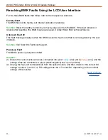
Resolving BMK Faults Using the LCD User Interface

For the three BMK faults that follow, refer to their respective solutions.

Factory Fault

The BMK has lost its factory-set internal calibration reference.

Solution:

 Reset the battery monitor by removing all power from the BMK. If the fault remains or 

returns after resetting, the BMK may require repair. Contact Solar Stik Technical Service.

Unknown Fault ##

This fault message displays when the BMK has sent a fault code that is not recognized by the user 
interface.

Solution: 

Call Solar Stik Technical Support.

Power-up Fault

The BMK’s power-up sequence failed.

Solution: 

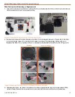
(1)  Ensure the current sense wires are connected into pins 1 (

blue

 wire) and 2 (

orange

 wire), and the 

voltage wires are connected to pins 3 (black/negative) and 4 (

red

/positive).

(2)  Unplug the four-port terminal block from the sense module, and then check for the correct DC 

voltage on pins 3 (-) and 4 (+). The voltage must be 7–70 volts DC, depending on the nominal 
voltage of the inverter.

Back to Quick 

Links page

Summary of Contents for 24VDC PRO-VERTER 5000-120 AGS

Page 1: ... 2020 Solar Stik Inc OPERATOR MANUAL FOR 24VDC PRO VERTER 5000 120 AGS Updated 20200618 Interactive DISTRIBUTION STATEMENT A Approved for public release distribution is unlimited P N 20 0104023 Version 1 0 ...

Page 2: ...2 Load Support automatic functions 12 Peak Power Delivery manual functions 12 UPS automatic functions 13 Selecting a Generator Grid AC Source 13 The Hybrid Model 13 The Load Support Model 14 The Peak Power Delivery Model 14 Energy Storage Requirements for Operation 14 DC Voltage 14 PRO Verter Circuits and Functions 15 Load Prioritization 16 Real time Load Management 16 Pass through Power and the I...

Page 3: ...ton Menus Read only Displays 39 SETUP Button Menus 40 TECH Button Menus 45 Quick Links to Statuses Faults and Resolutions Reported by the PRO Verter 46 Quick Links to PRO Verter Status Messages 46 Quick Links to Problems Solutions and Explanations 46 PRO Verter LCD Screen Troubleshooting Table 47 PRO Verter Inverter Mode Status Messages 48 PRO Verter Charge Mode Status Messages 49 PRO Verter Charg...

Page 4: ...re 12 PRO Verter Faceplate 27 Figure 13 LCD user interface 29 Figure 14 Inverter Charger ON OFF Buttons 29 Figure 15 PRO Verter System Status LEDs 30 Figure 16 User Interface Menu Buttons 31 Figure 17 How to start stop a generator manually 32 Figure 18 Powering up the PRO Verter 33 Figure 19 Setting the PRO Verter clock 33 Figure 20 Menu buttons on the LCD user interface 37 Figure 21 CC CV HOLD CV...

Page 5: ... critical loads when the primary power source fails Reducing generator burdens fuel consumption wet stacking maintenance or logistic support Durations of silent operation are critical Use of renewable power generation is desirable Less reliance on grid utility power is desirable peak shaving Temporary replacement of inadequate grid or generator power during periods of peak power demand peak power ...

Page 6: ...his manual provides an overview of the core feature functions and capabilities of the PRO Verter along with a complete overview of the menu options but there are many functional properties within the programming menus that are not covered The PRO Verter programming can be easily adjusted for changing conditions If the system architecture is altered changes to system functions or if the operational...

Page 7: ...O Verter 5000 220 AGS Read all instructions and safety information contained in this manual While the PRO Verter is designed for indoor outdoor operation the user interface control panels must not be exposed to rain snow moisture or liquids Close and latch and or lock the cases when the equipment is unattended The PRO Verter is not field serviceable If repair is needed contact your field service r...

Page 8: ...s no representations or warranties regarding the use of the System in connection with life support systems or other medical equipment devices Safety Information Labels Your safety and the safety of others is very important Always read and obey all safety messages This is the safety alert symbol This symbol alerts you to potential hazards that can kill you or hurt you and others All safety messages...

Page 9: ...rs labs and telecommunication rooms Using the Fire Extinguisher When using the extinguisher on a fire remember PASS Pull the pin Aim the nozzle or hose at the base of the fire from a safe distance Squeeze the operating lever to discharge the fire extinguishing agent Sweep the nozzle or hose from side to side until the fire is out Move forward or around the fire as the fire diminishes Watch the are...

Page 10: ...ctrocution Always Work with another person in case an emergency occurs Disconnect power before performing maintenance Wear safety glasses whenever working on any part of a System that requires exposure to mechanical or direct electrical contacts WARNING The 24VDC PRO Verter 5000 120 AGS is NOT GFCI protected WARNING Standing water around the electrical equipment and or intrusion of water into the ...

Page 11: ...rator controls and closed at all other times Impact Equipment should not be dropped onto hard surfaces at a height greater than one foot when transporting or during operation Dust Foreign Object Intrusion Air intake filters should be cleaned once per month or more frequently when conditions warrant As a general rule minimize exposure to high levels of particulates and foreign object debris by exer...

Page 12: ... operator with a flexible architecture that allows for the addition of multiple power sources such as renewable power generation Load Support automatic functions Operating conditions The Surge Load AC requirement is MORE than the Generator Grid AC output but less than the Inverter AC output rating In the Load Support model the Load Support model allows the use of a smaller generator based on total...

Page 13: ...ower sources and can be easily programmed to work with the amperage limits of both the AC source circuits and the AC load circuits Once programmed the PRO Verter effectively calculates and then regulates how much power is delegated between these circuits to prevent overload conditions while maintaining prioritizing the load Acceptable generators grid AC sources for use with a single PRO Verter sho...

Page 14: ...tries A minimum of four 4 energy storage modules i e Expander Paks or Power Paks must be present and functioning for the PRO Verter to be able to operate at its rated power DC Voltage The PRO Verter has an intelligent brain that uses one primary data point for most of its critical operating decisions battery bus DC voltage The Inter Connect Circuit communicates VOLTAGE Voltage is the one value tha...

Page 15: ...cuit Recovery Circuit AC powered System Recovery overdischarged batteries NATO Circuit DC Load or Battery Charging circuit Both the primary and the support circuit functions of the inverter charger are managed by native programming which can be easily adjusted through settings made at the User Interface If the PRO Verter is connected to an over discharged battery the recovery circuit enables the P...

Page 16: ... power will be directed prioritized to the load reducing DC flowing from the batteries prolonging battery operation time and the reducing need for AC from a grid utility or generator source If a PRO Verter is being used with a fuel driven generator the AGS circuit can be used to control the generator when the battery SOC is low Once the battery SOC reaches a determined point the PRO Verter AGS cir...

Page 17: ...ter use If the PRO Verter is being used with grid utility power the transfer switch allows the PRO Verter to control multiple conditions under which power is harvested including time of day peak shaving or other condition based on application requirements The transfer switch is directly controlled by the inverter function but it ONLY reacts to the presence of incoming AC power from a generator or ...

Page 18: ...l blink rapidly Once the AC voltage is accepted the AC transfer relay closes passing AC power to the load and then CHARGE function begins indicated by a steady on CHG LED at the User Interface and the LCD will show CHARGING The PRO Verter is equipped with a logic controlled multi stage battery charger It actively monitors battery voltage and SOC using this information to control the amount of powe...

Page 19: ...eries to the loads rather the loads connected to the inverter are powered directly using the external AC power pass through power However if power from the external AC source is interrupted the inverter senses these conditions and immediately starts inverting to maintain AC output to the loads Only a manual deactivation of the inverter function will cause the LED to turn off If the inverter functi...

Page 20: ...the generator either has not started or has not provided the correct run gen sense signal voltage to the AGS module after four 4 start attempts See also Table 1 Testing the AGS Function There is a red AGS TEST button at the AGS interface that can be used to confirm that all wiring from the generator to the AGS module is correct and the AGS circuit is configured correctly for a particular generator...

Page 21: ... parameters it will shut down and attempt to protect itself the battery bank and the AC loads If there is a condition that causes the inverter to shut down it will be reflected as a FAULT with the indicator LED in a steady on state The LCD will display an error message with the fault code reason Refer to the Troubleshooting Procedures section to help diagnose and clear the fault condition Note Cir...

Page 22: ...rrent to the ESMs to decrease temporarily to allow the charger to cool down See additional information Meter Circuits The PRO Verter accurately tracks and provides data in both real time and historical format It has dedicated menus in the METERS programming for both the AC and DC circuits which will aid in troubleshooting issues or verifying system performance The Battery Monitor BMK meters employ...

Page 23: ...circuit It ensures the potential for a reverse polarity connection within the circuit is minimized If a problem occurs in a leg of the Inter Connect Circuit the affected leg will disconnect from the primary network leaving the other circuits functioning If a major failure occurs in the circuit then the entire network will shut down for System and Operator protection Operate with Voltage The Inter ...

Page 24: ... AGS Operator Manual Figure 7 Inter Connect Plug The Inter Connect Plug Polarized 200 A maximum current 24 VDC connection only Mechanically locks into place Rotate knob clockwise to lock counterclockwise to release Can be repaired or modified in the field ...

Page 25: ...ch C USB Ports for device charging no data USB 5 VDC 2 1 D AMMPS Comm Port MS3452W14S 28 E TQG Comm Port Amphenol HA100001 02 36 F Tech Port Ethernet RJF21B G Air Intake A A B Description Connector Voltage Amps A Input Connection customer per application HBL503SS 125 VAC 50 B Air Exhaust A E B B Connections and Cooling Figure 9 PRO Verter 5000 120 AGS left exterior Note Ports vary among PRO Verter...

Page 26: ... Inter Connect Port 24 VDC 200 C D Air Intake A D B The Information Plate I Plate provides concise but abbreviated information for setting up and running a System All system components should be connected as shown in the diagram on the I Plate The diagram illustrates component connections but not the actual physical arrangement of the components for a specific application The Information Plate Fig...

Page 27: ...hese LEDs are active but do not report the status of the generator Auto Generator Start AGS Alarm ON OFF Switch In the ON position an alarm will sound as warning that the generator has initiated the auto start protocol and is about to start The OFF position disables the alarm for silent operations Auto Generator Start AGS Test Button The Test Button is a push button momentary switch that allows th...

Page 28: ...breaker is green when the circuit is operating normally Remote Monitoring Kit RMK This optional sold separately device reports records and stores 28 PRO Verter and System metrics See Remote Monitoring Kit section RMK Connections Ports and Cables These provide communication connections between the RMK the PRO Verter and remote access monitoring equipment via the Tech Port See Remote Monitoring Kit ...

Page 29: ...rter programming can be adjusted accordingly When configuring or making changes to a PRO Verter programming it is important to understand the individual settings found in the menus and how each one can affect overall system operation or individual functions within the PRO Verter itself Consult with Solar Stik Technical Support if changes are necessary Rotary SELECT Knob Menu Buttons LCD LED Status...

Page 30: ...nt is automatically decreased because 1 Charger Back off the inverter s internal temperature is getting hot and the current is decreased to reduce maintain temperature or 2 Low AC Input Voltage the input AC voltage is low and the charger is disabled to help stabilize incoming AC voltage to prevent AC disconnect BLINKING display does not show any charge status The inverter is detecting and qualifyi...

Page 31: ... provides quick access to AC related controls METERS The METERS menu is mostly a read only medium and can provide both live and historical data for the PRO Verter functions It can provide real time data as well as performance indicators for troubleshooting SETUP The SETUP menu contains the prime programming for PRO Verter operation Nearly every function the PRO Verter manages can be accessed and c...

Page 32: ...3 Gen Control Select Set Gen Control AUTO Rotate to desired selection To change or check a setting first press a menu button then use the SELECT knob to navigate to the desired menu item The diagram below illustrates how to use the menu buttons and the SELECT knob to move between and within various menus The diagram below illustrates how to change the generator control The options OFF ON and AUTO ...

Page 33: ... hour Rotate the dial until desired minute appears Press down SELECT knob to set minute Rotate the dial until desired AM or PM appears Press down SELECT knob to set AM or PM For normal sustained operation the PRO Verter must be connected to a 24 VDC power source such as 24VDC Li Expander Paks to power up When the PRO Verter powers up the master control board that commands the various internal circ...

Page 34: ...apable of meeting the full demand that the PRO Verter s AC INPUT setting allows The total AC load must be rated for continuous power that is less than the total power the AC INPUT setting allows The total DC loads must be rated for continuous power that is less than the maximum DC AMPS that are available when in CHARGE mode Proper Loading and Power Distribution The PRO Verter can serve as a power ...

Page 35: ...output It is typically used in operations where the PRO Verter is connected to a generator or Grid AC power source that is rated for LESS AC output than the Inverter output power rating of the PRO Verter It automatically engages once the load exceeds the AC INPUT setting FAVS 03 and because it requires power from the batteries it should only be used if the excessive loads are brief in duration and...

Page 36: ... issues are mitigated 5 Use the PRO Verter Meter and Tech menus to determine where a fault condition exists 6 Contact your FSR The most common PRO Verter performance problems are due to temperature issues The PRO Verter batteries power generation and even the loads are all adversely affected by heat so mitigating the affects of heat will only improve system performance Clean air filters regularly ...

Page 37: ... Button 01 System Setup 01A Set Clock 01B Screen Setup 01C Temp Display 01D Max Charge 02 Inverter Setup 02A Search Watts 02B LBCO Setting 02C AC In Time 02D AC In VDC 02E AC In SOC 02F Power Up 03 Charger Setup 03A AC Input 03B VAC Dropout 03C Battery Type 03D Absorb Done 03E Max Charge Rate 03F Max Charge Time 03G Final Charge 03H EQ Reminder 04 AGS Setup 04A Gen Run VDC 04B Gen Run Time 04C Gen...

Page 38: ...rt Volts Delay 15 sec Set CV Chg Done HOLD CV CHG VDC Set CV Charge Volts 29 0 Set Max Charge AMPS 110 Orange menu items indicate values set by Solar Stik for a specific application These values with the exception of setting the clock to local time should not be changed by the user without consulting tech solarstik com Green menu items represent factory default settings read only settings or optio...

Page 39: ...t 100 SOC Available Statuses Windows in 04A 05A BMK Status 05B Battery SOC Think n BMK Ready No Comm Factory Fault Power up Fault Unknown Fault Think n Factory Fault Power Up Fault Unknown Fault 05C DC Volts BMK 28 28 VDC 05A Statuses 05B Readings 05D DC Amps BMK 140 ADC 05E DC AH In Out 10 AH 05F Reset AH In Out AH 05G Total AH Out AH 05H Minimum VDC VDC 05I Maximum VDC XXX VDC 05J Days Since 100...

Page 40: ...1 18AM Set Screen Setup Pwr Save 15 min 02 Invert Setup 02A Search Watts OFF 02B LBCO Setting Volts 24 4 02C AC In Time 6 00A to 6 00P 02D AC In VDC Range 22 0 28 0 VDC Set Search Watts Range OFF 5 50 Set LowBatCutOut Volts 18 0 24 4 Set Connect Hour 12 00A Set Connect Minute 12 00A Set Connect AM PM 12 00P 02E AC In SOC 80 100 Set Connect SOC 20 99 Set Disconnect SOC 21 100 Set Disconnect AM PM 1...

Page 41: ...rolled Set Max Charge Time 12 0 Hrs Set Final Charge Stage Silent Set Final Charge Stage Float Set Final Charge Stage Multi Range Time Amps SOC Range 0 1 to 25 5 Hrs Range 0 to 250 ADC Range 50 to 100 03D Absorb Done CC CV Controlled Set Absorb Done Time 1 0 Hrs Set Absorb Done Amps 20 ADC Set Absorb Done SOC 100 Set Absorb Done Time Set Absorb Done Amps Set Absorb Done SOC 03E Max Charge Rate 100...

Page 42: ...PM 00 00A Default OFF Set Stop Gen Hour 1 00P Set Stop Gen Minute 00 45P Set Stop Gen AM PM 00 00P Set Stop Gen Hour 12 00P Set Stop Gen Minute 00 00P Set Stop Gen AM PM 00 00P Set Start Gen AC Amps OFF Set Start Amps Delay 0 sec 127 min 04C Gen Run Amps Press Select Set Stop Gen AC Amps 18 0 32 0 Set Stop Amps Delay 0 sec 127 min Default OFF Set Stop Gen AC SOC 21 100 04D Gen Run SOC Press Select...

Page 43: ...5P Set Start Quiet AM PM 0 00P 04G Quiet Time OFF Set Quiet Time ON Set Start Quiet Hour 1 00 12 00PM Set Start Quiet Minute 0 00P Set Start Quiet AM PM 0 00A Default OFF Set Stop Quiet Hour 1 00P Set Stop Quiet Minute 00 45P Set Stop Quiet AM PM 00 00P Set Stop Quiet Hour 12 00P Set Stop Quiet Minute 00 00A Set Stop Quiet AM PM 00 00A Set Quiet Time Topoff 30 120Min Set Quiet Time Topoff Off 04I ...

Page 44: ...Range Off 1 255 continued SETUP 05 BMK Setup 05A Charge Eff Auto 05B AmpHour Size 360 AH 05A Charge Eff Range Auto 50 99 05B AmpHour Size Range 200 2500 Default Auto BMK Setup Notes The AmpHour Size value should be set according to the total capacity of the battery bank minus 10 For example one 24VDC Li Expander Pak 2400 is 100 Ah The minimum setting allowed on the PRO Verter is 200 Ah The state o...

Page 45: ...s F Specific fault listed if no fault No Fault History displays H1 the most recent fault H2 H9 are the faults in the earliest past record with H9 being the oldest 04B AGS Faults Press Select 04C PT Faults Press Select 04D Clear Faults Press Select 04D Clear Faults in seconds 04D Clear Faults HISTORY CLEARED Press and hold SELECT for 5 seconds If Yes only a 3 digit number displays 07 Show ALL Menus...

Page 46: ...tatuses Faults and Resolutions Reported by the PRO Verter This guide is interactive if used on a computer or handheld device Each of the faults in the lists below is touch linked to an explanation of the fault and a solution to resolve the fault BMK Statuses BMK Not Present BMK Ready No Comm Think n AGS Statuses AC In Gen Cooldown Gen Warm up Manual Run No Comm Off Quiet Time Ready Start VDC Quick...

Page 47: ...rrect cable installed between the two ports on the RMK See PRO Verter Remote Monitoring Kit RMK LAN Operator Manual Display shows unrecognized letters or symbols Static electricity may have been discharged into the LCD screen Refresh display Press and hold the SELECT knob for 10 seconds LCD text is locked up pushing any button has no response Connections on communication cable are not making a goo...

Page 48: ...itch has it in Standby until the external source is disconnected No Inverter Comm The LCD user interface is not receiving any communication data via the PRO Verter s Internal Circuit Network Solution The inverter may need to be serviced Contact Solar Stik Technical Support Off This message tells indicates that there is no AC available on the inverter s AC output The inverter function is OFF and th...

Page 49: ...ttery voltage increases rapidly toward the maximum programmed charge voltage 29 0 VDC The lower the battery voltage the higher the current Constant Voltage This is the period when the battery voltage approaches its programmed maximum voltage value The charging current declines as the battery approaches its full charge capacity The generator is programmed to automatically stop the fuel driven gener...

Page 50: ...erator still runs until the FAVS F5 Gen Run VDC Set Stop Gen 1 Minute and cooldown Setup 04J time is met Note Most faults inverter AGS and BMK also alternate with the inverter charger status Charger Standby This indicates the charger has been disabled to prevent further charging but the AC power from utility or generator to the AC input is still available on the AC output This display is shown whe...

Page 51: ...n Check the METER 01A DC Volts and METER 01B DC Amps meter values on the LCD screen It should be close to the maximum rated or programmed charge current if the battery voltage is under 28 8 VDC on 24 volt models Check the Meter SETUP 03A AC Input Amps setting and ensure that it is set in accordance with system requirements Charge amps are lower than expected or is 0 amps DC Solution The charge rat...

Page 52: ...ad on the PRO Verter output has exceeded the inverter s AC current protection limits This fault may occur because the connected AC loads are larger than the inverter s output capacity due to unauthorized equipment being used on the platform surge loads are present there is a wiring short on the output or the output wires are incorrectly installed Solution If the overload condition lasts for less t...

Page 53: ... 5 VDC difference If not ensure all connections are tight and the power switch on each Expander Pak is turned on 2 Restart the System using the System Recovery Button Function See Restart a System with Overdischarged Batteries for instructions This fault automatically clears once current flows into the battery from the PRO Verter battery charger this may take anywhere from a few minutes to a few h...

Page 54: ...turned off to prevent the batteries from being overdischarged The fault message displays and the FAULT red LED illuminates when the battery voltage drops below the LBCO Setting FAVS F4 value for more than one minute This fault may occur when 1 the generator failed to start or 2 Other charging sources are offline or inadequate The fault will clear and the inverter will automatically restart and res...

Page 55: ...has proper ventilation and the PRO Verter cooling fans are working and that the air filters are clean Shade the PRO Verter from exposure to direct sunlight Solar loading is a major source of heat buildup inside the PRO Verter Stuck Relay This fault message displays when the inverter is inverting but the internal AC pass through relay that should be open while inverting is closed Solution The AC pa...

Page 56: ...is not closed while charging Solution If one of these internal faults occurs the inverter will require an inverter or power reset to clear the fault After resetting the inverter press the INVERTER ON OFF button on the user interface to turn the inverter on and then verify that the fault has cleared i e manual restart If the internal fault remains or returns the inverter may require repair at a Sol...

Page 57: ...knob The top line shows 04A AGS Status and the bottom line displays the current status of the AGS An AGS status of Off or Ready indicates the user interface and the inverter is communicating with the AGS If the AGS status is not Off or Ready then refer to section Resolving AGS Operational Statuses or section Resolving AGS Faults Using the LCD User Interface for assistance before continuing Startin...

Page 58: ...in the gray box would appear only if the PRO Verter were programmed differently They are shown only as a reference Back to Quick Links page Start Amp Generator has autostarted based on the SETUP 04C Gen Run Amps setting Start Exercise Generator has autostarted based on the SETUP 04H Gen Exercise setting Start SOC Generator has autostarted based on the SETUP 04D Gen Run SOC setting Start Temp The A...

Page 59: ...Once the AGS status indicates Warm up the PRO Verter s AC input ignores any incoming AC power This prevents the PRO Verter from loading the generator during warm up Once the AGS has determined that the generator is running the warm up time setting must be met before the generator can connect to the PRO Verter Manual Run Generator started manually from a start stop switch directly connected to the ...

Page 60: ...tting down the generator successfully started and ran for more than two 2 minutes but the generator unexpectedly stopped before the active AGS autostop condition was finished This fault occurs when the generator is overloading as a result of 1 unauthorized equipment being used on the platform and or 2 surge loads are present Note The AGS controller determines the generator is running by monitoring...

Page 61: ...fault codes adequate fuel and refer to the generator Operator and Maintenance Manual If the generator starts reconnect it to the System and attempt to start it manually ON using the PRO Verter control CTRL 03 If the generator does not start using the PRO Verter controls ensure proper electrical connections between the PRO Verter and the generator and refer to the PRO Verter Operator Manual Note On...

Page 62: ...t is determined be sure to enable the AGS to autostart Go to the CTRL 03 Gen Control menu and select AUTO Once the fault is cleared and the reason for the fault is determined the AGS again to see if the fault returns or test the AGS generator system by performing the AGS functional test How to Clear AGS Fault History Go to the TECH 04 Fault History menu press the SELECT knob and then turn the knob...

Page 63: ...MK is not communicating with the inverter user interface The following SOC statuses indicate the battery s current state of charge SOC Access the METER 05B Battery SOC menu to view the BMK s current SOC status Think n When the BMK sense module is first connected the batteries need to be fully charged i e SOC 100 to establish a SOC reference point The BMK sense module is disconnected from power and...

Page 64: ...ik Technical Service Unknown Fault This fault message displays when the BMK has sent a fault code that is not recognized by the user interface Solution Call Solar Stik Technical Support Power up Fault The BMK s power up sequence failed Solution 1 Ensure the current sense wires are connected into pins 1 blue wire and 2 orange wire and the voltage wires are connected to pins 3 black negative and 4 r...

Page 65: ... that is network connected to be cleared erased Refer also to the TECH 04 Fault History 04D Clear Faults menu See the diagram below Rotate the SELECT knob to display the second and third screens for the particular fault shown on the first screen After viewing all screens for the fault continue to rotate the SELECT knob to display earlier faults as applicable First screen The top line displays the ...

Page 66: ...ntil 04 AGS Meters or 05 BMK Meters is displayed AGS and BMK Meters represent the only data sets for the generator or the battery system that is cumulative The DC and AC meters indicate current status information only Inverting 01 DC Meters LCD Display Meter Button Rotary Select Knob Status 01 DC Meters METER press Top line shows inverter charger status Bottom line shows current menu heading Press...

Page 67: ...This meter does not replace the hour meter for total hours the generator has run AGS Temp This feature is not enabled in the PRO Verter 5000 Days Since Gen Run This menu displays the number of days since the generator has last run This menu is useful in determining if the AGS start and stop settings are set up correctly Note This meter resets whenever the generator is either auto started exercised...

Page 68: ...displayed DC Amps BMK This meter displays the real time charge current amps into battery or discharge current amps out of the battery as measured through the BMK shunt Charging is shown as a positive number and discharging is shown as a negative number The range is from 0 1 to 999 amps 1 0 AH In Out This meter displays the Ah returned to or removed from the battery When this value is positive it r...

Page 69: ... is shown After this value has been reset the display will begin monitoring and showing new minimum DC input values If the battery monitor is not connected or not communicating the display will show 0 0 Maximum VDC This menu displays the highest battery voltage since the last reset The voltage shown on the display is averaged each second and this allows a check if the charging system battery charg...

Page 70: ... of 24VDC PRO Verter 5000 M 1 Inspect case for visible damage and missing items 2 Clean excessive dust or dirt accumulation from the exterior interior and connectors 3 Close all unused port covers If the case is broken or split or if connectors are damaged do not place into service 2 Air Intake Filters M1 M 2 1 Remove the three 3 air intake vent covers to expose the filter material See PRO Verter ...

Page 71: ...r Replace the filter if it is damaged arrows in Figure 23 If the filter is in good shape clean it by rinsing it with water to remove the particulate matter and dry it Replace the filter if it is crushed rotted or cracked as illustrated in the left column of Figure 23 3 Reinstall the clean dry filter or install the new filter replacements may be stored behind PRO Verter I Plate Secure the louvered ...

Page 72: ...ng enough that any remaining moisture inside will dry When it is dry reintegrate the component to the System and test it to determine if it is still functional WARNING Standing water around the electrical equipment or intrusion of water into the System components can increase the risk of electrical shock Water Intrusion Prevention and Remediation The lid on the PRO Verter should be closed whenever...

Page 73: ...itch until the red FAULT LED turns off and the CHG LED is constant green no longer blinking 8 Return 03E Charge Rate to 100 AFTER at least four 4 batteries have a green battery status LED 9 Charge all batteries fully 10 Turn on AC output breakers on the PRO Verter Faceplate to support loads The amount of time required for the CHG LED to become solid green Step 7 above will vary depending on the de...

Page 74: ... of the PRO Verter see below Locate the RESET button on the right side of the control board 3 Press and hold the RESET button for approximately ten 10 seconds until the RESET LED comes on and flashes rapidly 4 Once the rapid flashing has begun release the RESET button The RESET LED will go off after the RESET button is released Info The RESET button is a small momentary type switch that operates b...

Page 75: ...perator Manual Accessories PRO Verter Remote Monitoring Kit RMK LAN Item 20 0702602 24VDC 5 Inter Connect Cable P N 13 0000032 Available in custom lengths 24VDC 5 Inter Connect Strip 7 P N 13 1000160 PRO Verter Remote Monitoring Kit RMK AMMPS AGS Item 20 0702604 ...

Page 76: ... Verter The RMK also records and stores all of the data from the PRO Verter and provides tabular and graphical reports of these data in a user friendly browser based User Interface If an RMK is installed ensure that the connections are as shown below See the Operator and Maintenance Manual for the RMK for detailed information RJ11 CROSSOVER TO INVERTER RJ11 CROSSOVER TO REMOTE 24 VDC Power Connect...

Page 77: ...A 1 USB 5 A Breakers may vary with Custom Port Types Fuse s 2 3 A internal Weights and Dimensions L x W x H Weight 105 lb 46 3 kg Dimensions 27 5 x 19 75 x 13 90 in 69 9 x 50 x 35 3 cm Inverter Specifications 25 ºC 77 ºF Nominal AC Output Voltage 120 VAC Single Phase AC Output Voltage Tolerance 3 Input Current 60 AAC Output Frequency and Accuracy 60 0 5 Hz Continuous Output Power 4000 VA Inverter ...

Page 78: ...newable energy power generation systems with detailed explanation of system components Advanced configuration options with hands on deployment of actual systems will enhance student understanding Solar Stik New Equipment Training on site teaches Hybrid System configuration options with hands on deployment of actual systems to enhance student understanding Solar Stik Training Courses are tailored t...

Reviews: