|
87
December 2020
|
Solar Stik
®
, Inc.
System Setup and Operation Manual for the Solar Stik G-BOSS E Light HPS
PRELIMINARY
Item #
Item to be
Inspected
Interval
Procedures
Non-mission Capable
1
Visual
inspection
of 24VDC
Power Hub
2400
M
1. Inspect case for visible damage
and missing items.
2. Clean excessive dust or dirt
accumulation from the exterior,
interior and connectors.
3. Close all unused port covers.
~If the case is broken or split or
if connectors are damaged, do
not place into service.
2
Air Intake
Filters
M
1
1. Remove the air intake vent covers
to expose the filter material. (See
Power Hub Manual for location of
air intake filters.)
2. Wash with water and dry the filter.
Reinstall.
3. If the filter is damaged or cannot
be cleaned replace.
~If the filter cannot be cleaned,
is too damaged to function
properly and a replacement is
not immediately available, the
unit is partially mission capable.
Replace the filter as soon as
possible to restore the unit to
fully mission capable.
1
Clean or replace more frequently when the System is operating in dusty, windy environments
Table 15. 24VDC Power Hub 2400 PMCS
24VDC Power Hub 3500 PMCS
screws
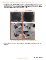
Figure 52. Cleaning the air intake filter
The air intake vent and filter are on the back of the Power Hub. The louvered vent cover is secured
by two (2) cross tip screws, one on each side. A fine cross tip screwdriver or angle driver will be
required to remove the screws (Figure 52A). After exposing the filter (Figure 52B), lift it from the
vent and wash thoroughly with water, dry thoroughly and reinstall Figure 52C). IF THE FILTER IS
DAMAGED REPLACE IT INSTEAD. Spare filters may be stored behind the Power Hub I-Plate.
Ensure the leading edge of the louvers are facing downward.
A
Power Hub Filter Removal and Cleaning or Replacement
B
C


