TECHNICAL HELPLINE 01684 774000
TECHNICAL HELPLINE 01684 774000
Step 4: Connecting the cable to your battery
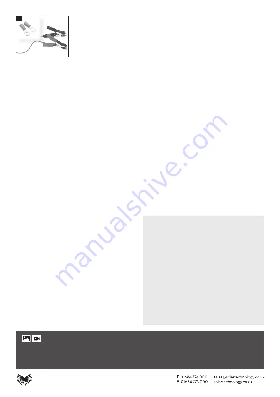
4.1 If wishing to fit crocodile clips (supplied in all 5, 10 and 20w kits) strip the red and black insulation (3cm) from
the inner cable ends. Attach the cable to crocodile clips by following the same procedure as described in
1.5
.
4.2 For a more secure connection and recommended for every panel of 30w and above, strip the red and black
insulation (6cm) from the inner cable ends, twist the bare wire and wrap around the battery terminals and
fix into position using your battery clamps. Some clamps have connection screws fitted, in which case, if the
supplied ring terminals have been crimped onto the wire ends, simply attach using your battery clamp screws.
4.3 When connecting to a battery always observe correct polarity.
Step 5: Additional information for fitting a MH kit
5.1 If the MH and PB kits have been selected, attach the brackets to the
side of the panel using the supplied stainless steel screws, ensuring
the brackets are flush with the top of the solar panel frame (thereby
leaving a gap between the bottom of the panel frame and the
roof). If the AE kit has been selected, please refer to the instructions
supplied with this fitting kit.
5.2 Place the panel on the roof position where it is to be fixed and draw
a pencil line around the footprint of the brackets or profiles (if PB or
AE kit has been selected). Ideally the panel should be fixed above
the cable entry hole.
5.3 Clean the area on your motorhome, caravan or boat where each
bracket or profile (if PB or AE kit has been selected) and the cable
feed gland is to be fixed with spirit, and make sure the area is clean,
oil free and dry.
5.4 Insert the cable trailing from the solar panel junction box into the
cable feed gland, ensuring the locking nut is loose, and then into the
entry hole on the roof. Using the provided bonding agent, now bond
the cable feed gland into position.
5.5 Apply the bonding agent (around a 6mm thickness of bonding
agent is ideal) to the edge of each bracket or profile (if PB or AE kit
has been selected) and then, possibly with assistance, turn the panel
so that the solar cells are facing upwards and bond the panel to the
roof, positioning the brackets in the pencil lines previously marked.
5.6 Once the cable has been pulled through the cable feed gland, the
gland nut should be tightened to affect a water tight seal.
5.7 Now the cable can be channelled into the roof lining or into
trunking/capping or similar and down to the battery. Finally, go to
Steps 2, 3 and 4 to complete the installation.
NOTE – bonding agent requires 24 hours to properly cure. We
would therefore recommend that the motorhome, caravan or boat is
not moved during this period.
Step 6: Additional information for fitting a Narrow Boat Ktt
6.1 The brackets are supplied with stainless self-taping screws to fix
the bracket to the roof of the narrow boat. Use the bracket itself as
a template and mark the hole centres. Be sure to measure the gap
between brackets to suit the solar panel.
6.2 Once the drill hole points have been marked drill piolet holes and
then apply a 6mm bead of bonding agent approx. 5mm inset from
around the edges of the bracket and a zig zag line in the middle.
Squirt a blob in the piolet holes.
6.3 Place the brackets onto the surface and push down so the bonding
agent just squeezes out beneath the edge of the bracket base.
Quickly insert the screws through the bracket holes and tighten up
but not too tight so it compresses the bracket against the sealant.
6.4 Leave the brackets to cure for 24 hours and then fully tighten the
screws.
6.5 The panel can then be fitted to the bracket and the cable gland
installed as per 5.4 and 5.6 above
6.6 The charge controller should then be fitted as per Step 2, 3 and 4.
Options
Connecting an inverter into the system
7.1 Should you require your solar system to power 240v appliances,
you will need to connect an inverter. Select an inverter power
(measured in watts) that is most appropriate for the power of your
appliances (also measured in watts). The inverter will be ideally
positioned reasonably close to the battery. Most inverters come
with pre-fixed cable so fix the loose end directly onto the battery
terminals (positive to positive / negative to negative) - contact
01684 774000 for more information.
Connecting two or more solar panels together
8.1 Should you wish to increase the power and make a solar array
or increase the voltage (to produce 24volt instead of 12 volt)
this can easily be achieved. Please contact Solar Technology on
01684 774000 and request a copy of our “Creating a Solar Array”
technical bulletin, which can also be found in the ‘file download’
section at www.solartechnology.co.uk.
Adding a second battery
9.1 If a second battery is used, it can be connected to the Charge
Controller, using terminals I (Fig. 3), by means of an additional
piece of 2-core, 1mm cable (not supplied). As in step 4.6 above,
attach the other cable to the second battery, not forgetting to add
a fuse on the positive line as descibed in step 5 above. Power from
the Charge Controller will be diverted to the second battery only
when the primary battery is fully charged.
Warranty
Solar Technology International rigid solar panels are supplied with a 10 year panel
build warranty and 20 year cell performance warranty.
10 Year Build Warranty
This guarantees the panel from mechanical failure and water ingress during this
period. The frame will not buckle under normal conditions nor will the glass crack
unless outside force has been used.
20 Year Cell Performance Warranty
The solar cells are guaranteed to perform for the long term and this warranty
specifically confirms that by year 20 the cells will be outputting no less than 80%
of their new value. For example, a 100wp solar panel is guaranteed to deliver no
less than 80wh by year 20 when tested under Standard Test Conditions.
In the event of a successful warranty claim in both cases, Solar Technology
International will, at its discretion provide one of the following remedies;
1.
Replace the defective solar panel or
2. Refund the percentage of the cost of
the solar panel to the customer representing the percentage of the time period
between new and year 10 and in the case of a claim on the cell performance a
percentage will be paid according to the power output less than 80%.
Solar Technology International Ltd does not accept liability for any 3rd party
damage how so ever caused or any costs associated with the return of faulty
products.
Solar Technology International Limited
Unit 6, Station drive, Bredon, Tewkesbury GL20 7HH
4
We want your photos and videos!
Here is your chance for you and your solar panel to be a star! Just send in pics or videos of you and your solar panel in a great location and if selected we will not
only give you ever lasting recognition on our online favourite users wall of fame but we will send you a Freeloader Sixer, 6000mAH solar power bank worth £70 completely free!
Please send to
hello@solartechnology.co.uk including your address details and best of luck!
Note – we cannot guarantee to publish every entry and only those selected by our marketing department for publication will be awarded a Sixer. By providing your images you
automatically grant us the right to use these images or videos howsoever we see fit.


