Heating control - user manual
www.solarcontrols.cz
Instructions for the installation and setup
of the device
Page 10 of 58
CONFIGURATION A
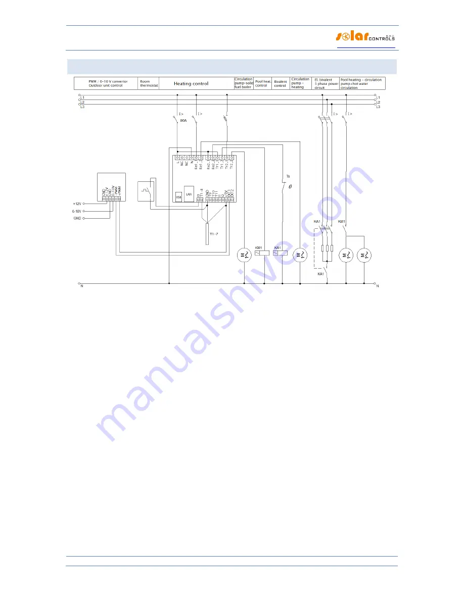
Figure 2: Electrical diagram of configuration A. A PAST® storage tank is used; the heat sources primarily include an outdoor unit of a heat
pump with direct condensation in the tank and a bivalent electrical heat source and also a solid fuel boiler without its own electronic
control; heat consumers include flow heating of hot water in the tank, one heating circuit with classic radiators and one heating circuit
for heating the pool by means of a pool heat exchanger. The power of the outdoor unit is controlled by a 0-10 V signal via a PWM/0-10V
converter. The temperature of the heated premises is controlled by a room thermostat with PI control. The circulation pump of the solid
fuel boiler is switched on directly by the controller, the same applies to the circulation pump of the heating circuit. The circulation
pumps of the pool heating circuits are switched on by the KM1 auxiliary relay. The bivalent heat source in the storage tank is switched
on by the KA1 4-pole contactor, which at the same time switches off all work conductors on the basis of protection by an independent
mechanical Ts thermostat mounted in the upper part of the storage tank (ČSN EN 60335-1). A total of 7 digital temperature sensors are
connected.


