338
Solectria
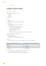
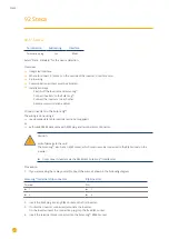
90.4 Solectria V4
Termination
Addressing
Interface
Yes
Yes
RS485
Selection available under Solectria V4
The following types are to be connected according to this diagram:
•
PVI 14TL
•
PVI 20TL
•
PVI 23TL
•
PVI 28TL
•
PVI 36TL
•
PVI 50TL
•
PVI 60TL
Overview
•
Integrated interface
•
Where to connect: Terminal strip inside the inverter.
•
4-pin wiring.
•
The communication address has to be assigned.
•
Installation steps
•
Switch off the inverters and the Solar-Log™.
•
Connect inverters to the Solar-Log™.
•
Connect the inverters to each other.
•
Allocate communication address.
Address range 1 to 254
Settings on the inverter‘s display according to the manufacturer‘s manual.
Connect inverters to the Solar-Log™.
The wiring is done using a
•
self-made cable connection with terminal block connector.
•
Where to connect: Terminal strip inside the inverter.
Procedure
1. If you are making the cable yourself, connect the wires as shown in the following diagram:
Solar-Log™ terminal strip connector
RJ45 inverter
Terminal
PIN
►
1 A/Data+
►
RS485+
►
3 GND
►
GND
►
4 B/Data-
►
RS485-
2. If no further inverter is connected, terminate the inverter according to the instructions for the inverter.
3. Insert the terminal block connector into the Solar-Log™ RS485 socket.
Connect the inverters to each other.
•
Connect using a network cable (patch cable).
•
Where to connect: RJ45 sockets inside the inverter.
Summary of Contents for Solar-Log
Page 1: ...1 Components Connection Manual V 4 2 3 Solar Log EN ...
Page 20: ...20 01 Inverter ...
Page 398: ...398 Appendix 113Appendix 113 1 SMA mixed wiring Fig SMA mixed wiring ...
Page 402: ...402 02 Meter ...
Page 444: ...444 03 Battery Systems ...
Page 456: ...456 sonnen Note Only one battery system can be connected to a Solar Log device ...
Page 463: ...463 04 Heating rods ...
Page 470: ...470 05 Heating pumps ...
Page 478: ...478 06 Sensors ...
Page 488: ...488 07 Pyranometer ...
Page 495: ...495 08 Smart Plug components ...
Page 502: ...502 09 Power Charging Stations ...


