399
Appendix
113.2
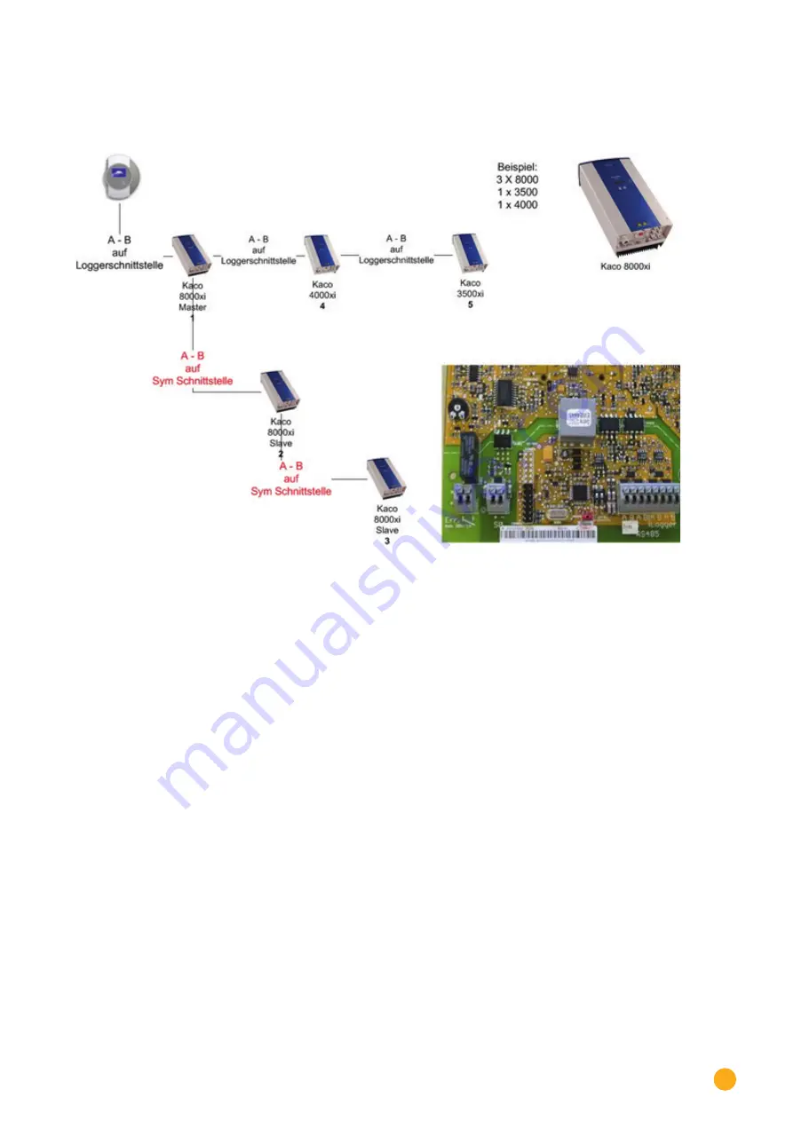
Interconnection of Kaco Powador inverters
Fig.: Interconnection of Kaco Powador inverters
Instructions for Powador 6400xi and 8000xi
•
Interconnection of Powador 6400Xi and 8000xi:
►
Set 1 inverter as „Master“, 2 as „Slaves“;
Read the labeling on the inverter circuit board!
►
Clamp the Solar-Log™ data cable to the „LOGGER“ terminal strip on the Master inverter.
►
Also connect the inverters to each other through the „SYM“ terminal strip
►
Connect any additional inverters through the „Logger“ terminal strip
►
On the inverter operating display:
Set the communication addresses, numbering consecutively
►
On the inverter operating display:
Switch „SYM Bus“ to active
•
Powador 6400Xi and 8000xi stand-alone mode:
►
Set the inverter to „Slave“, irrespective of labeling on the circuit board
►
Clamp the Solar-Log™ data cable to the „SYM Bus“ terminal strip
►
On the inverter operating display:
Switch „SYM Bus“ to inactive
►
On the inverter operating display:
Set the communication addresses, numbering consecutively
Summary of Contents for Solar-Log
Page 1: ...1 Components Connection Manual V 4 2 3 Solar Log EN ...
Page 20: ...20 01 Inverter ...
Page 398: ...398 Appendix 113Appendix 113 1 SMA mixed wiring Fig SMA mixed wiring ...
Page 402: ...402 02 Meter ...
Page 444: ...444 03 Battery Systems ...
Page 456: ...456 sonnen Note Only one battery system can be connected to a Solar Log device ...
Page 463: ...463 04 Heating rods ...
Page 470: ...470 05 Heating pumps ...
Page 478: ...478 06 Sensors ...
Page 488: ...488 07 Pyranometer ...
Page 495: ...495 08 Smart Plug components ...
Page 502: ...502 09 Power Charging Stations ...


