464
EGO Smart Heater
1
EGO Smart Heater
1.1
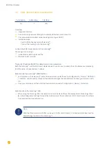
EGO Smart Heater (RS485)
Termination
Addressing
Interface
Yes
No
RS485
Overview
•
Integrated interface.
•
Where to connect: Terminal strip inside the heating rod.
•
3-pin wiring.
•
The communication address does not have to be assigned.
•
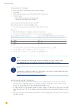
Installation steps:
•
Switch off the heating rod and Solar-Log™.
•
Connect the heating rod to the Solar-Log™.
Connect the EGO Smart Heater
to the Solar-Log™:
The wiring is done using a
•
self-made, shielded 3-wire data cable and terminal block connector.
General information on managing and prioritizing the EGO Smart Heater via smart energy
The Solar-Log™ can manage and prioritize up to six EGO Smart Heaters with the smart energy function.
The connection of the Smart Heaters can be made in different ways.
Two examples should clearly illustrate the options:
Example 1
Six heating rods are connected via the Ethernet option; it is not possible to connect any additional heating rods via
the RS485 interface.
Example 2
One heating rod is connected per interface via the RS485 A and RS485/422 B interface. This allows four heating
rods to be connected via Ethernet.
Note
Only one EGO Smart Heating can be operated per RS485 interface.
Summary of Contents for Solar-Log
Page 1: ...1 Components Connection Manual V 4 2 3 Solar Log EN ...
Page 20: ...20 01 Inverter ...
Page 398: ...398 Appendix 113Appendix 113 1 SMA mixed wiring Fig SMA mixed wiring ...
Page 402: ...402 02 Meter ...
Page 444: ...444 03 Battery Systems ...
Page 456: ...456 sonnen Note Only one battery system can be connected to a Solar Log device ...
Page 463: ...463 04 Heating rods ...
Page 470: ...470 05 Heating pumps ...
Page 478: ...478 06 Sensors ...
Page 488: ...488 07 Pyranometer ...
Page 495: ...495 08 Smart Plug components ...
Page 502: ...502 09 Power Charging Stations ...


