472
CTA Heat Pumps
Overview (Siemens OCI Adapter)
•
Where to connect: Connection terminals in the OOCI adapter.
•
3-pin wiring.
•
Communication address is set to „1“ by default on the controller side..
•
Installation steps:
•
Switch off the OCI adapter and the Solar-Log™.
•
Connect the OCI adapter to the Solar-Log™.
Connect the Siemens OCI adapter to the Solar-Log™
The cabling meets the requirements of RS485 wiring:
•
+ and - via a twisted pair of wires preferably shielded, GND any cable.
Procedure
1. Open the OCI adapter according the manufacturer‘s instructions.
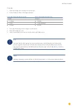
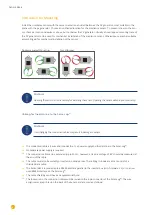
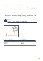
2. Connect the wires for the cable connection as shown in the following diagram:
Solar-Log™ terminal strip connector
Siemens OCI adapter terminal connection block
Pin
Pin
►
1 Data+
►
+
►
3 GND
►
G
►
4 Data-
►
-
3. Terminate the OCI adapter with the DIP switches (both both DIP switches set to „ON“).
4. Close the OCI adapter according the manufacturer‘s instructions.
5. Insert the terminal block connector into the Solar-Log™ RS485 socket.
Note
The CTA service partner installs the signal lines to the Siemens controller in the heat pump.
The installer takes care of the signal line connection to the auxiliary relay or Solar-Log™.
Note
A license code is required to activate the CTA heat pump. This code has to be purchased from Solare
Datensysteme GmbH. Go to the following WEB site:
https://www.solar-log.com/en/solutions-service/licenses/
Detection via the Solar-Log™ WEB Interface
•
To control the heat pump, a detection must be carried out at Solar-Log™,
select the device class „Switch“
under the menu
Configuration | Device | Definition | Interface
with the plus symbol and then select „So-
lar-Log™“ as the manufacturer. Confirm the selection by clicking on „
OK
“.
.
•
For data acquisition of the heat pump, repeat the step by clicking on the plus symbol, select device class „Heat
pump“ and then select „
CTA
“ as the manufacturer and the interface on the heat pump (OCI adapter). Click on
„
OK
.“ .
•
Save your selections and then start the Device Detection under
Configuration | Device | Detection
and start
the device detection.
Summary of Contents for Solar-Log
Page 1: ...1 Components Connection Manual V 4 2 3 Solar Log EN ...
Page 20: ...20 01 Inverter ...
Page 398: ...398 Appendix 113Appendix 113 1 SMA mixed wiring Fig SMA mixed wiring ...
Page 402: ...402 02 Meter ...
Page 444: ...444 03 Battery Systems ...
Page 456: ...456 sonnen Note Only one battery system can be connected to a Solar Log device ...
Page 463: ...463 04 Heating rods ...
Page 470: ...470 05 Heating pumps ...
Page 478: ...478 06 Sensors ...
Page 488: ...488 07 Pyranometer ...
Page 495: ...495 08 Smart Plug components ...
Page 502: ...502 09 Power Charging Stations ...


