486
Sensor Box Professional Plus
3.3
Mechanical Installation Optional Sensors
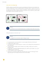
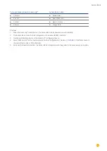
The temperature sensor should be mounted with a wall bracket at a shadowy location. The 3-pin connector must
be screwed into the irradiance sensor.
The wind wheel should be mounted with the mounting angle at the highest and most exposed location. The 2-pin
connector must be screwed into the irradiance sensor.
Attention!
The cables of the optional sensors can not be extended. The sensor must be mounted horizontally.
3.4
Wiring the Data Cable with the Solar-Log™
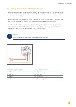
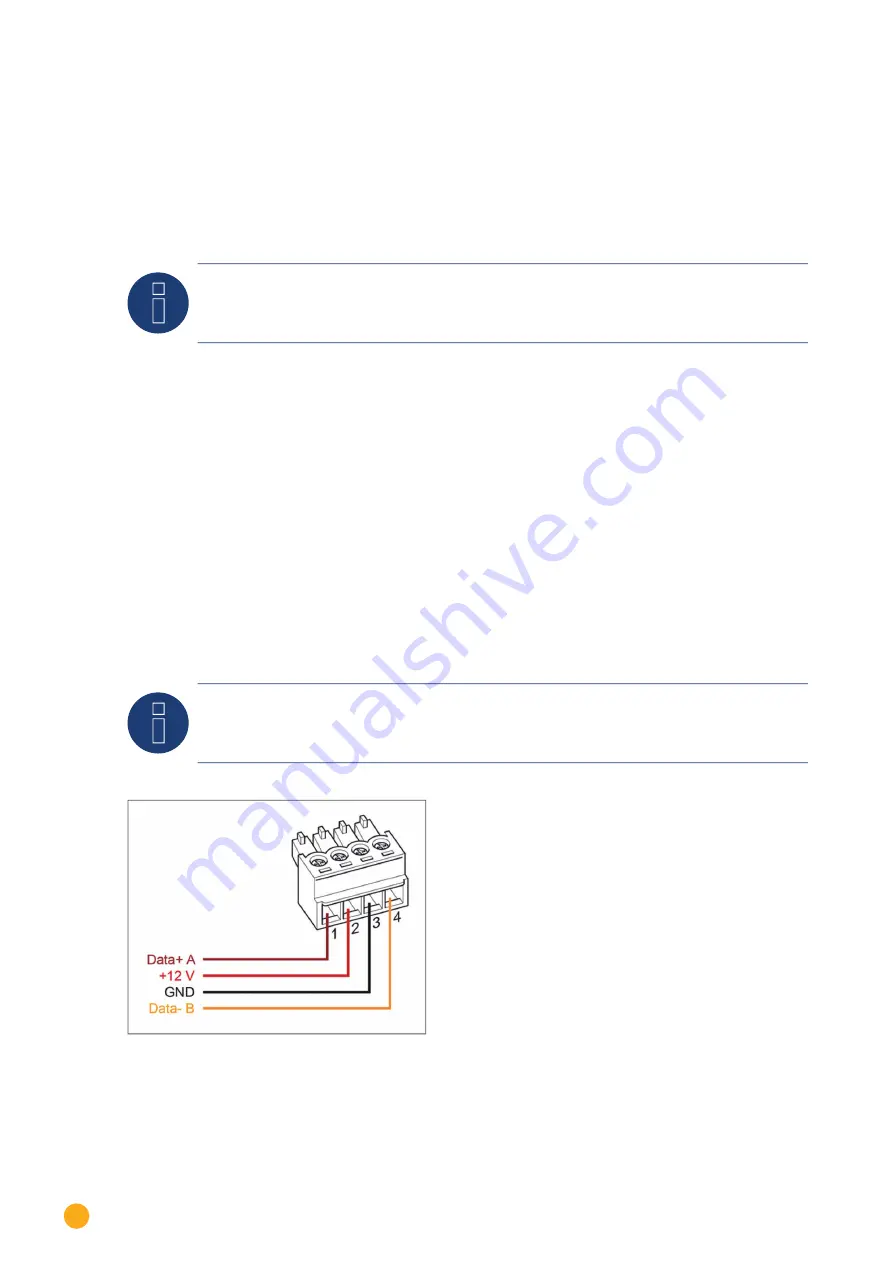
The Sensor Box Professional Plus is connected via the RS485 gateway with the Solar-Log™. The 4-core connection
cable between the irradiance sensor and the Solar-Log™ is used for data exchange and 12 V power supply. A sepa-
rate mains adapter is not necessary.
The connection cable can be extended (max 50 m). Please be sure that the supply voltage 10,5 VDC reaches the
end of the connection cable. For longer distance please use a cable with bigger wire cross section.
For outdoor use, the connection must be protected in conformity with IP54. For indoor wiring, please use a
shielded data cable. The shield of the cable must be connected with a potential equalisation. The 4 wires of the
connection cable have to be connected with the Solar-Log™ connection plug.
Warning!
Interchanging the connection cables may result in damage to sensor.
Summary of Contents for Solar-Log
Page 1: ...1 Components Connection Manual V 4 2 3 Solar Log EN ...
Page 20: ...20 01 Inverter ...
Page 398: ...398 Appendix 113Appendix 113 1 SMA mixed wiring Fig SMA mixed wiring ...
Page 402: ...402 02 Meter ...
Page 444: ...444 03 Battery Systems ...
Page 456: ...456 sonnen Note Only one battery system can be connected to a Solar Log device ...
Page 463: ...463 04 Heating rods ...
Page 470: ...470 05 Heating pumps ...
Page 478: ...478 06 Sensors ...
Page 488: ...488 07 Pyranometer ...
Page 495: ...495 08 Smart Plug components ...
Page 502: ...502 09 Power Charging Stations ...

