UPS for 400 Vac Grid, Installation Guide, doc. rel. 3.0
25
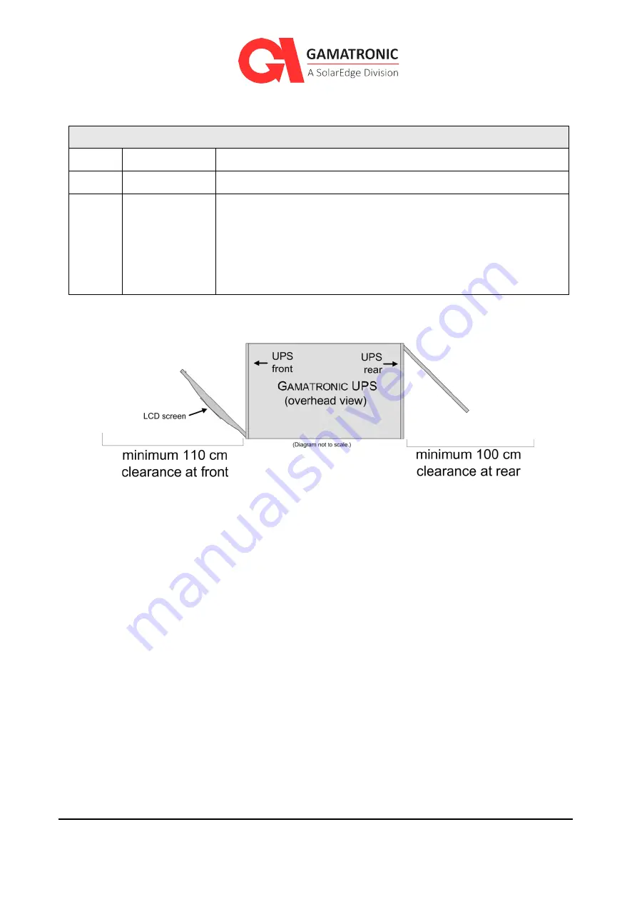
Table 3: Recommended clearances
R
ECOMMENDED MINIMUM CLEARANCE AROUND THE
UPS
Front
110 cm (43 in.) Minimum adequate clearance for user access and service.
Rear
100 cm (39 in.) Minimum adequate clearance for cable connections.
Sides
--
No minimum clearance provided that the UPS is not placed next
to heat-emitting or electronic equipment. If the UPS is placed
next to heat-emitting or electronic equipment, leave at least 20
cm free space between the UPS and the other equipment. The
object here is to avoid subjecting the UPS to additional heat and
to protect the UPS from stray electronic signals.
Figure 8: Recommended clearances around the UPS
3.3.3.
Site Preparation
–
Electrical
Perform the following procedures before connecting any external cables to the UPS.
To perform the electrical site preparation procedure:
1.
Read Chapter 5, Circuit Breaker Selectivity. The chapter includes considerations
regarding the size of the external circuit breakers on the rectifier input and bypass input
lines.
2.
Verify that circuit breakers on the electrical panel that supplies the UPS are compliant
with local and national codes and Gamatronic system specifications.
3.
Verify that the input and output power cable connections, ground, and neutral lines
comply with local and national codes and are appropriate for the circuit breakers
protecting them.
4.
Measure the ac input voltage. Phase-to-phase voltage (measured between L1-L2, L2-L3,
and L3-L1) should be 400 Vac ±10 %. Phase-to-neutral voltage (measured at L1, L2, and
L3) should be 230 Vac, ±10 %.


