background image


UPS for 400 Vac Grid, Installation Guide, doc. rel. 3.0 

35 


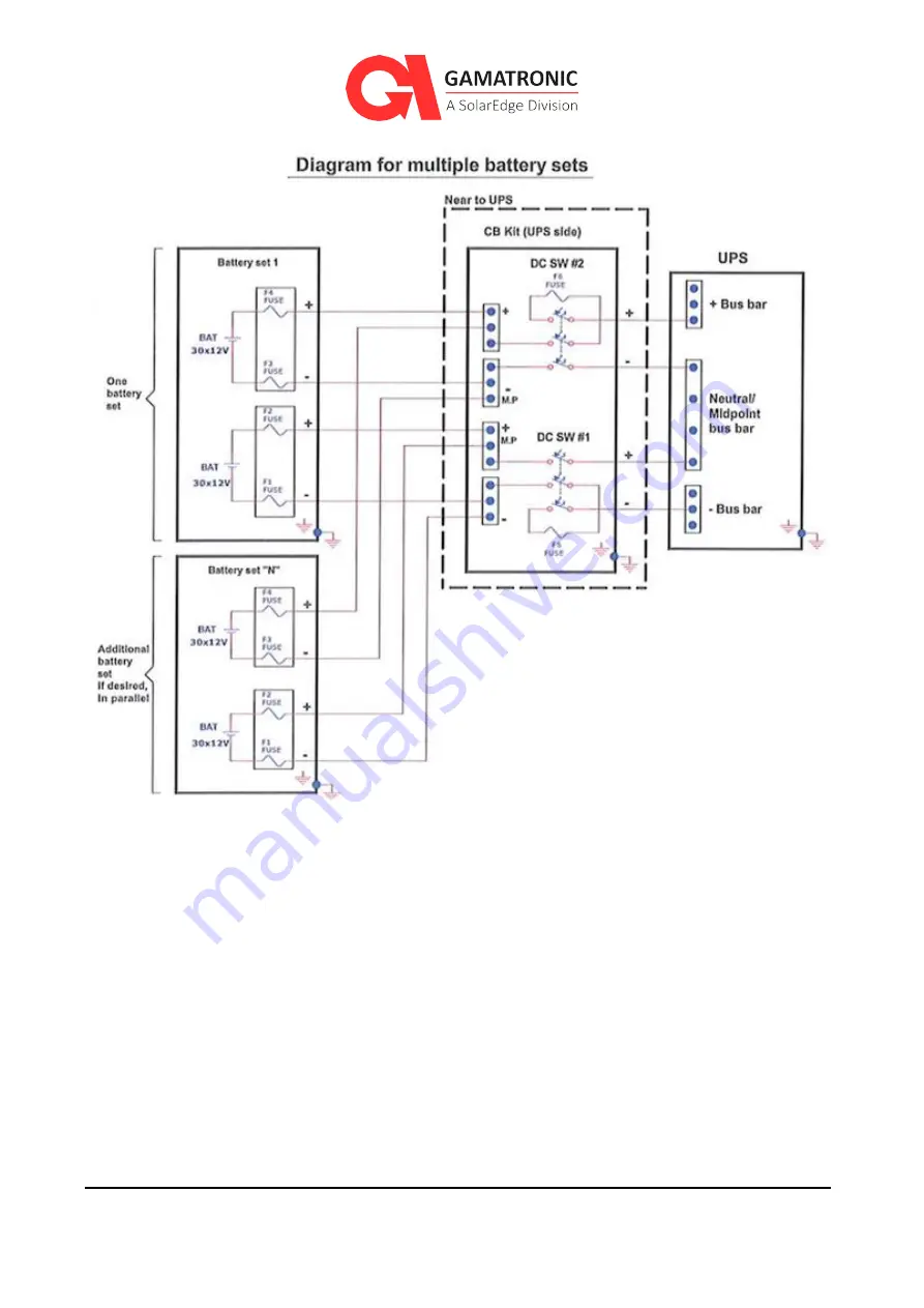
Figure 13:  Connecting multiple battery sets, using CBs 

Figure 13 shows how two battery sets can be connected to the UPS. This example includes two 
circuit breakers (DC SW #1 and #2), one for each battery pole.  

Fuses F5 and F6 in Figure 13 have the same values as those specified in Figure 12. 

The rating in Figure 13 of Fuses F1 through F4, and of DC SW #1 and #2 (for each battery set 
Figure 12), depends on the number of battery sets. The greater the number of battery sets, the 
lower the rating required for fuses F1 through F4. Fuses F5 and F6 and DC SW# 1 and #2 (Figure 
13)
 must be rated according to the DC current rating of the system to safely disconnect the 
batteries. 

Protect the batteries from moisture, dampness, and foreign substances.  

The temperature of the battery's surroundings influences the batteries' useful lifetime. 

Summary of Contents for Gamatronic B300

Page 1: ...GAMATRONIC THREE PHASE MODULAR UPS FOR THE 400V GRID B300 INSTALLATION GUIDE Revision 3 0 January 2020 Doc 2MUM B300I This installation guide is for product 101SKD60 ...

Page 2: ...ii UPS for 400 Vac Grid Installation Guide doc rel 3 0 Remember to register your product at http www gamatronic com product warranty in order to activate your warranty ...

Page 3: ...ific system in any particular environment Operation and control of the UPS is accomplished through a touch sensitive LCD display screen In this manual when explaining how to navigate the control software via the touch sensitive screen the terms tap press choose and select may be used interchangeably to indicate selection of a screen option Most of the electrical abbreviations in this document are ...

Page 4: ...eries 33 3 3 5 Powering up the system 37 3 3 5 1 Before starting up the UPS 37 3 3 6 Initial Configuration 38 3 3 6 1 System Startup Wizard 38 3 3 6 2 Continuing first time startup process 42 3 3 6 3 Assigning IP Address to the UPS 49 3 4 TESTING 52 3 4 1 Test Self loading PQ mode 52 3 4 2 Test Under load 55 3 4 3 Test Battery and blackout mode 56 3 4 4 Test ATS 56 3 4 5 Test ECO Mode 58 3 4 6 Tes...

Page 5: ...TION 77 6 2 1 Maintenance bypass for parallel systems 85 7 PROCEDURE MAINTENANCE BYPASS MODE 86 7 1 CIRCUIT BREAKER LAYOUT 87 7 2 TRANSFERRING THE UPS TO MAINTENANCE BYPASS MODE FROM NORMAL MODE 88 7 3 TRANSFERRING THE UPS BACK TO NORMAL MODE FROM MAINTENANCE BYPASS MODE 90 8 USING THE UPS WITH A GENERATOR 91 8 1 THE AUTOMATIC TRANSFER SWITCH ATS 91 9 SERVICE AND REPAIRS 93 ...

Page 6: ...18 EXIT CONFIGURATION WIZARD 41 FIGURE 19 FLAT CABLES 42 FIGURE 20 STATIC SWITCH 42 FIGURE 21 MODULES ON SCREEN 43 FIGURE 22 MODULES OFF SCREEN 43 FIGURE 23 MODULES ON SCREEN 44 FIGURE 24 CONFIRM DISCONNECTING THE LOAD 45 FIGURE 25 CONFIRM SWITCH ON ALL MODULES 45 FIGURE 26 THE ALARMS ICON INDICATES ALARM CONDITIONS 46 FIGURE 27 NEXT SCHEDULED TEST SCREEN 46 FIGURE 28 BATTERY TEST IN PROGRESS SCRE...

Page 7: ...IONS AT INSIDE REAR OF THE SYSTEM 76 FIGURE 55 COMMON DC PARALLEL COMMUNICATION CABLE 79 FIGURE 56 DECENTRALIZED DC PARALLEL COMMUNICATION CABLE 79 FIGURE 57 THE SYSTEM MENU SCREEN 80 FIGURE 58 THE CROWN ICON INDICATES THE MASTER UPS 81 FIGURE 59 AC OUTPUT VOLTAGE DISPLAY FOR A SINGLE MODULE 81 FIGURE 60 CONNECTION DIAGRAM FOR 2 PARALLEL UNITS 83 FIGURE 61 CONNECTION DIAGRAM FOR 4 UNITS IN PARALLE...

Page 8: ...CIRCUIT BREAKERS 34 TABLE 6 BATTERY LIFETIME VS ENVIRONMENTAL TEMP ILLUSTRATIVE AS PER EUROBAT 36 TABLE 7 KEY TO FIGURE 47 64 TABLE 8 DESCRIPTION OF CONNECTOR GROUP 2 KEY TO FIGURE 48 65 TABLE 9 CABLE SETS FOR PARALLEL COMMUNICATION BETWEEN UPSS 78 TABLE 10 RATING OF CB12 FOR MAINTENANCE BYPASS OPTION 85 TABLE 11 NORMAL MODE OPERATING POSITION OF THE CIRCUIT BREAKERS 88 TABLE 12 POSITION OF THE CB...

Page 9: ... 2 Inspect the ShockWatch and TiltWatch devices which are adhered to the outside of the wooden packing crate Verify that their indicators are not red A red indicator is a sign of rough handling ShockWatch or tip over TiltWatch Notify the carrier and Gamatronic Support immediately if rough handling of the UPS is suspected or if any damage is found or suspected 3 Retain the shipping crate and packag...

Page 10: ...subject to shock or tip over 4 Using a forklift move the shipping crate close to the place in which the UPS will be installed 5 Cut and remove any straps that are on the shipping crate 6 Stand on a secure ladder and use an electric screwdriver to remove the screws that are holding the roof of the shipping crate in place Then remove the roof ...

Page 11: ...ove the walls themselves leaving the UPS standing on its wooden shipping pallet Figure 4 Remove the walls of the crate 8 Cut and remove any straps that are securing the UPS to the shipping pallet 9 Remove the plastic wrapping and all other packaging material from the UPS Be careful to avoid scratching the finish of the Modular UPS 10 Lift the UPS from the shipping pallet and move it to the locatio...

Page 12: ...nt injury to personnel or even death Ensure all power is disconnected before performing installation or maintenance See Table 3 and Figure 7 for recommended clearances The UPS must be well grounded to the building s grounding system with a conductor that has a current carrying capacity that matches the rating of the UPS according to local codes Battery installation battery maintenance and battery ...

Page 13: ...ed to the ac input Take appropriate precautions during installation inspection and servicing Don ts Do not open the cover of the UPS or the battery cabinets under any circumstances All UPS panels and doors should be closed Do not insert any objects through the ventilation holes Do not put objects on the UPS Do not move the UPS while it is operating Do not use the UPS outdoors Do not turn the UPS u...

Page 14: ... do not reinsert the module immediately Wait five minutes WARNING RISK OF LETHAL ELECTRIC SHOCK This UPS receives power from more than one source Disconnection of all ac sources and dc sources is required to de energize this unit before servicing WARNING RISK OF LETHAL ELECTRIC SHOCK Do not touch uninsulated battery terminals ...

Page 15: ... 3 0 7 3 System Structure and Installation The UPS is composed of Up to 10 power modules each providing 30 kVA 30 kW Static switch module System controller Maximum output capacity of the UPS is 300 kVA 300 kW Figure 5 Major UPS components front view ...

Page 16: ... group 1 E Dry contacts and communication connections Connector group 2 F Main ac and dc connections G BYPASS INPUT terminals L1 L2 L3 reading from back to front H AC INPUT terminals L1 L2 L3 reading from back to front I AC OUTPUT terminal connections L1 L2 L3 reading from back to front J BATTERY connections positive midpoint neutral negative reading from back to front N Neutral bus bar same as Mi...

Page 17: ...le 2 Key to Figure 6 Item Description 1 Bypass Input L1 2 Bypass Input L2 3 Bypass Input L3 4 Ac Input L1 5 Ac Input L2 6 Ac Input L3 7 Ac Output L1 8 Ac Output L2 9 Ac Output L3 10 Positive battery terminal 11 Battery midpoint and Neutral bus bar 12 Negative battery terminal Protective earth ground bus bar ...

Page 18: ...AMILIAR WITH THE LOCAL ELECTRICAL CODES AND REGULATIONS IMPROPER WIRING MAY CAUSE INJURY TO PERSONNEL AND OR DAMAGE TO THE EQUIPMENT IN THE EVENT THAT THE UPS HAS BEEN DISCONNECTED FROM THE AC MAINS FOR FOUR MONTHS OR LONGER FOLLOWING ITS DELIVERY TO THE CUSTOMER SITE THE UPS MUST BE CONNECTED TO THE AC MAINS AND OPERATED WITH NO LOAD FOR A PERIOD OF FOUR HOURS BEFORE APPLYING A LOAD ...

Page 19: ...on the status screen is the Phase to Neutral voltage The Neutral line MUST be connected to the UPS on the input and output stages of the UPS The UPS will support phase to phase loads and phase to Neutral loads The Neutral line must always remain connected when the UPS is operating All input output and dc cables must be armored and the armored layer must be connected to the UPS ground connection te...

Page 20: ...endor and to Gamatronic Support gamatronic com INSTALLATION CHECKLIST FOR THE GAMATRONIC MODULAR UPS Customer Address Site Phone E mail Serial numbers System _________________Static Switch ____________________ Modules 1___________ 2___________ 3___________4___________ 5___________ 6___________ 7___________8___________ 9___________ 10___________ Technician Name Date Signature Activity Requirement R...

Page 21: ...e way in Verify that each module makes a mechanincal connection with the power backplane on the inside rear of the shelf 3 Slide out each Power module by about 7cm enough to unplug them from the power backplane and attach the right and left ribbon cables between the modules and the base Fully slide the bottom module securly into the base ...

Page 22: ...nsation No condensation dampness 3 3 2 6 Check ventilation Proper airflow to batteries 3 3 2 7 Check foundation and access Adequate structure for weight and access 3 3 2 8 Check for adequate clearances easy access See Figure 8 Recommended clearances around the UPS 3 3 2 Comments on site preparation physical __________________________________________ ________________________________________________...

Page 23: ...erify polarity 400 V and 400 V 8 14 Connect ground neutral rectfier ac input bypass ac input and ac output cables to the UPS acording to Figure 9 or Figure 10 Ground input neutral rectifier and bypass inputs and output cables are connected 3 3 3 15 Assemble all battery connections in the battery cabinet with the appropriate protective devices according to Figure 12 Batteries are assembled and read...

Page 24: ... SW4 open OFF Verify polarity in each battery set 19 3 Switch ON SW1 and SW2 and measure the voltage across SW3 and SW4 If the voltage difference across SW3 or SW4 is greater than 10V charge the battery set that has the lowest difference until the differences across SW3 and SW4 are less than 10 V 19 4 Turn off all battery CBs Batteries are connected and OFF Negative pole to midpoint has a negative...

Page 25: ...g multiple battery sets add the Ah value of the of sets 24 Enter your local time zone 25 Press the Finish button The controller restarts with the new configuration 26 From the Main Screen choose Profile and verify that the system is configured as per your requirements or with acceptable default values Verify time and date are correct The system configuration matches your requirements Comments on s...

Page 26: ...the 2 flat cables then slide in fully and select only this module and turn it on main operation on off modules on 6 Once fully operational fully shut it down and insert the next power module 7 Repeat this process for each additional power module first time installation 8 After each module has been individually powered up and shutdown preform a complete shutdown of the system main operation on off ...

Page 27: ...ld be no greater than 2 Vac OK Not OK record value ____________ V 33 Go to Main Status STSW Detail1 Verify that Bypass phase sequence field says Correct 34 For each BYPASS phase use the mesurments taken in 30 32 and use the following formula to compute the acceptable phase to ground voltage range Voltage between L and N voltage between N and Gnd voltage between L and G If the voltage difference is...

Page 28: ...G OK Not OK record value ____________ V 42 With the system in inverter mode measure the voltage difference between the bypass line and the ac output line L1 L1 L2 L2 L3 L3 The difference should not exceed 60 V OK Not OK record phase and value ____________ V 43 Manually transfer the load to bypass then to inverter and then back to bypass again OK Not OK 44 If the output is not with in the acceptabl...

Page 29: ...for 5 10 minutes 6 Change 70 of max kW power and 70 of max kVAr power 7 Run for 5 10 min 8 Transfer system to VF mode main operation PQ mode 51 Battery mode test Verify that the system is running in normal mode the output is supplied from the inverter then disconnect AC input and see that inverters remain ON and output of the system is on inverter Return AC input 52 ATS test Verify the ATS is set ...

Page 30: ... Normal Mode 56 Verify that output voltage under load is 230V 2 57 Record load current L1 A L2 A L3 A 58 Connect the Ethernet cable Configures IP address time server and DHCP according to the preferences of the local IT team Main Setup Communications 59 Export the log and then clear the log ...

Page 31: ...ll sides and ensure that there is no visible damage to any portion of the cabinet the module housings or other coverings 2 Verify that the number of modules delivered is as ordered and that a system controller module and static switch module were delivered 3 Verify that the LCD display screen is undamaged The product you received will include a product inventory list Confirm contents included in t...

Page 32: ...the unit and battery cabinets 4 Verify that the foundation and access routes are adequate for the dimensions and weight of the UPS and battery cabinets 5 Ensure that there are adequate clearances to allow comfortable access to battery cabinets and electrical panels Recommended minimum clearances around the UPS are provided in Table 3 and Figure 8 6 It is recommended that the battery cabinets be lo...

Page 33: ...the UPS 3 3 3 Site Preparation Electrical Perform the following procedures before connecting any external cables to the UPS To perform the electrical site preparation procedure 1 Read Chapter 5 Circuit Breaker Selectivity The chapter includes considerations regarding the size of the external circuit breakers on the rectifier input and bypass input lines 2 Verify that circuit breakers on the electr...

Page 34: ... between the battery and the Gamatronic UPS For example the Ferraz Shawmut A70QS fuse F1 F2 F3 and F4 in Figure 12 and Figure 13 Be sure to verify proper phase order 8 For initial startup to take place the battery must be connected to the UPS and must be available 3 3 4 Cabling This section explains UPS cabling and connection requirements Warning the UPS leaves the factory with the bypass and rect...

Page 35: ...ct the neutral line Warning If you have a four pole mains to generator switching system you are in danger of having the neutral line disconnected when the four pole switch is operated This can result in the problems described above To avoid these problems it is strongly recommended that if you use a four pole mains to generator switching system you install an isolation transformer that constantly ...

Page 36: ...28 UPS for 400 Vac Grid Installation Guide doc rel 3 0 Figure 9 Recommended system connections Note For recommended circuit breaker and fuse ratings refer to Table 4 ...

Page 37: ...UPS for 400 Vac Grid Installation Guide doc rel 3 0 29 Figure 10 Recommended connections with input isolation transformer Note For recommended circuit breaker and fuse ratings refer to Table 4 ...

Page 38: ...e obtained by simply opening the back door and removing the bottom panel of the UPS To the electrical panel to which the UPS is connected affix a sign or label with the following warning WARNING There is a UPS attached to this electrical panel To avoid electric shock DO NOT DISCONNECT THE UPS s NEUTRAL LINE WHEN THE UPS IS OPERATING ...

Page 39: ...gure 9 or Figure 10 for circuit breaker recommendations refer to Table 4 For an overview of circuit breaker selectivity refer to Chapter 5 Warning Connection of The UPS to the electrical panel must be performed only by a licensed electrician experienced with similar systems Warning If two separate input lines are used for rectifier and bypass input as in Figure 9 and Figure 10 the Neutral line mus...

Page 40: ...S CB3 AMPS wires C S mm2 Use copper wire only AMPS wires C S mm2 Use copper wires only AMPS 30k 3 x 43 5 6 3 x 75 3 x 43 10 3 x 50 60k 3 x 87 16 3 x 120 3 x 86 25 3 x 100 90k 3 x 130 5 50 3 x 175 3 x 130 50 3 x 150 120k 3 x 174 50 3 x 225 3 x 173 70 3 x 200 150k 3 x 287 5 95 3 x 275 3 x 216 95 3 x 225 180k 3x260 120 3 x 325 3 x 260 120 3 x 300 210k 3 x 304 5 150 3 x 375 3 x 300 150 3 x 325 240k 3 ...

Page 41: ...ttached to the UPS 1 Ideally the external battery cabinet s should be located as close to the UPS as is practical 2 Assemble the batteries within the battery cabinet 3 Figure 12 shows the recommended connection to the UPS for a single battery set which includes two fuses inside of each battery cabinet One fuse should be placed on the plus line and one on the minus line of every 30 batteries The re...

Page 42: ... 220 264 308 352 396 440 FUSE A 50 100 150 180 220 260 300 350 400 400 7 The fuses between the battery cabinets and The UPS F1 F2 F3 and F4 in Figure 12 must be FAST FUSES SEMICONDUCTOR FUSES for example the Ferraz Shawmut A70QS fuse 8 For initial startup to take place the battery must be connected to the UPS and available Current values are for fuses F1 through F4 in Figure 12 and are based on 10...

Page 43: ...ure 12 The rating in Figure 13 of Fuses F1 through F4 and of DC SW 1 and 2 for each battery set Figure 12 depends on the number of battery sets The greater the number of battery sets the lower the rating required for fuses F1 through F4 Fuses F5 and F6 and DC SW 1 and 2 Figure 13 must be rated according to the DC current rating of the system to safely disconnect the batteries Protect the batteries...

Page 44: ... Vac Grid Installation Guide doc rel 3 0 Table 6 Battery lifetime vs environmental temp illustrative as per Eurobat ENVIRONMENTAL TEMPERATURE ACHIEVABLE PERCENTAGE OF BATTERY S RATED LIFETIME 20 C 100 30 C 50 40 C 25 ...

Page 45: ...rior to supplying power to the UPS 4 Verify proper polarity with a multimeter on external battery box terminals 5 Leave all battery and output circuit breakers in the OFF in position 6 Check to see if the bypass and rectifier input are linked If they are linked then you have to remove the Static Switch If they are not linked simply keep the bypass circuit breaker in the off position 7 Turn the byp...

Page 46: ...initially started up a series of configuration screens are presented on the LCD display panel You will be prompted to provide the UPS with basic system configuration information in order to enable initial operation of the UPS To perform initial UPS configuration 1 Activate the UPS After the UPS is activated the Start screen appears Figure 14 Initial configuration wizard Start screen 2 Write down t...

Page 47: ... Technician password you received form Gamatronic in the Password text input field and press OK Without a password you cannot continue The Battery Capacity screen appears Figure 16 Initial configuration wizard battery capacity in Ah The capacity is used by the UPS when it is in battery mode in order to calculate the amount of backup time remaining ...

Page 48: ...value of each battery bank must be added i e for 2 battery banks of 90Ah each you would enter a value of 180Ah 4 Indicate the capacity of the connected batteries in ampere hours Ah using the Battery Capacity slider then select Next This capacity figure is used by the UPS when it is in battery mode in order to calculate the amount of backup time remaining The Set Time Zone screen appears Figure 17 ...

Page 49: ...ac Grid Installation Guide doc rel 3 0 41 The Finish screen appears Figure 18 Exit configuration wizard 6 Select Finish The System Menu wizard exits 7 Continue the first time installation process See Section 3 3 6 2 ...

Page 50: ...that the parameter values are appropriate for the batteries you have chosen 2 Turn off the bypass and rectifier input circuit breaker Figure 19 Flat cables 3 Insert a single power module and connect the right and left flat cables If the bypass and input are bridged slide out the Static Switch at least 5 inches Figure 20 Static switch 4 If the bypass and input are bridged slide out the Static Switc...

Page 51: ... on the module System Menu Operation On off Modules on The Modules on screen appears Figure 21 Modules On screen Press Confirm 6 Select and shut down the module System Menu Operation On off Modules off The Modules Off screen appears Figure 22 Modules Off screen 7 Select the power module icon The selected power module is highlighted with a blue border ...

Page 52: ...ighlighted 12 Select Confirm 13 The selected power module is switched on Notice that the active power module is highlighted in blue and is active module 2 while the primary power module is in Standby State module 1 because it was shutdown 14 Once fully operational fully shutdown the power module just added and insert the next power module 15 Repeat this process for each additional power module dur...

Page 53: ...firm Switch on All Modules 22 Confirm OK 23 The system will transfer to bypass then once all inverters are fully operational the system will transfer the output to the inverter i e Normal Mode 24 Turn on the battery CB to the UPS and then verify battery voltage on the Status screen Main Status This may take a minute 25 Check input bypass output and DC voltages 26 Select Main to return to the Syste...

Page 54: ...ing Guide Figure 26 The Alarms icon indicates alarm conditions 28 Perform a brief battery test to verify that the UPS is ready and able to operate in battery mode when it is needed Operation Battery test Test battery The Test in Progress screen appears Figure 27 Next scheduled test screen 29 Press Test Battery The Test in Progress screen appears ...

Page 55: ...ion over all CBs 31 On the Status screen verify that the bypass and the inverters are synchronized This is the recommended stage at which to perform load testing before transferring the customers critical load to being supported by the UPS For load testing instructions refer to Testing Section 0 32 Transfer the unit to bypass Operation Transfer load Transfer to bypass The Transfer load to bypass a...

Page 56: ... UPS 36 Transfer the load to inverter Do not transfer the load to the inverter if the maintenance bypass circuit breaker is still in the ON position Operation Transfer load Transfer to inverter The Transfer load to inverter dialog appears Figure 30 Confirm Transfer Load to Inverter dialog 37 Press OK 38 Update the last maintenance date Main Setup System Maintenance Maintenance Alarms List Set last...

Page 57: ...igure 32 Confirm Save User Settings 42 Confirm OK The User Settings are saved The system is now supporting the load 3 3 6 3 Assigning IP Address to the UPS This procedure assigns an IP address to the UPS Assigning an IP address allows you to remotely monitor the UPS over an IP network If you do not want to remotely monitor the UPS you can skip this step If you decide to later implement remote moni...

Page 58: ... From the System Menu select Setup Connectivity Network Configuration The IP address configuration screen appears Figure 33 IP Address Configuration 2 Select Obtain an IP address automatically checkbox The IP Address Subnet Mask and Default Gateway text input fields are automatically populated 3 Click Confirm The UPS software has obtained an IP address To assign an IP address manually 4 From the S...

Page 59: ...S address 6 Type the addresses including digits and dots that make up the address using the virtual keyboard of the LCD panel in the appropriate text input fields To select an address field on the screen tap the field with your finger Depending on the particular model of screen on your system dragging your finger lightly across the field from right to left may yield best results 7 When you have co...

Page 60: ...The unit offers a self loading feature that removes the need for load banks or rewiring of the system 3 4 1 Test Self loading PQ mode This feature is available to do away with standard load bank requirements The unit can be configured to simulate resistive capacitive and inductive test loads In order to minimize site disturbance self loading should be performed with the output CB in the off positi...

Page 61: ...e 2 Select Enable and then select Confirm 3 PQ Mode is enabled 4 Transfer system from VF mode to PQ mode with 2 kW active load System Menu Operation Self loading PQ mode The Self loading PQ mode Setup screen appears Figure 36 Self loading PQ mode setup 5 Wait until system starts Self loading PQ mode 6 Navigate to System Menu Status ...

Page 62: ... active power in 10 increments After each time you raise the active load level press Confirm and wait 1 minute The load level can be incrementally raised to 95 98 kW of maximum system output power depending on the number of power modules in the system 9 Run the system for 5 10 minutes 10 If you want to test reactive simulated loads change the loads to 70 of max kW active power using the Active pow...

Page 63: ...s a UPS 3 4 2 Test Under load This test is designed for standard load bank testing to verify the operation of UPS under load To perform the test under load 1 Turn off all ac and dc CBs and isolate the system 2 Connect an average or standard load to the system 3 Turn on ac input CBs and measure the ac input voltage during operation under load Take the measurements at the output terminals of UPS pha...

Page 64: ...4 Test ATS If the input of the system is configured to run from both the grid and during grid power failure from the generator verify that the ATS Automatic Transfer Switch provides the full 10 second changeover time The system will transfer to battery mode when the grid feed is dropped Once the 10 second changeover time is complete and the generator has begun supplying ac the UPS will begin to op...

Page 65: ... Generator drop down menu choose dry contact 2 and select Confirm Now that it is enabled the battery charging current will be limited when the contact opens or closes depending on controller setting configuration To change system controller settings from default N O normally open to N C normally closed 1 From the System Menu navigate to input dry contact settings by choosing Main Setup Dry contact...

Page 66: ...ary power source 2 Verify that the ATS is set to 10 seconds transfer delay and it is fully operational 3 Disconnect the primary input feed 4 Verify that the ATS transfer time was greater than 10 seconds 5 Verify stability of UPS output 6 Verify limited charging current to the battery 2A 3 4 5 Test ECO Mode For customers looking to maximize efficiency the UPS can be configured to support ECO mode T...

Page 67: ... System System Type ECO Mode The Password screen appears 3 Type in the Gamatronic password key you received from Gamatronic support in the Password text input field 4 Click OK The ECO Mode screen appears Figure 42 ECO Mode screen Enabled checkbox 5 Select Enabled and then select Confirm The system returns to the System Type screen ECO Mode has been enabled The next step is to turn ECO Mode ON 6 Fr...

Page 68: ...de 7 Select ECO Mode off click for change 8 The ECO Mode off button is toggled on 9 The next step is to confirm ECO Mode is active 10 From the System Menu navigate to the Status screen The Status screen appears Figure 44 Status screen UPS ON and ECO Mode ON Notice the Status screen indicates UPS ON and ECO Mode ...

Page 69: ...operating system of the computer you are using To test IP communication with the controller 11 Use an RJ45 to RJ45 straight or crossed cable to attach a PC or laptop or other external computer to the Ethernet RJ45 port on the UPS s system controller 12 Configure the network connections of the external computer so that the computer is in the same domain as the UPS that is so that the first three no...

Page 70: ...62 UPS for 400 Vac Grid Installation Guide doc rel 3 0 The UPS System Menu should appear Figure 45 Web View This confirms IP communication with the controller ...

Page 71: ...ions They are grouped together on the front panel of the UPS in what is referred to as connector group 1 and connector group 2 See Figure 46 Figure 46 Location of Connector Groups 1 and 2 on the front of the UPS Location of connector groups 1 and 2 is shown in Figure 46 and close up views of the connectors are shown further on in the text where relevant ...

Page 72: ...ately goes into Bypass mode These contacts are intended to be used in conjunction with the Maintenance Bypass function They should be closed by the user s maintenance bypass switch to ensure that the UPS is in Bypass mode before moving to maintenance Bypass mode P28 Supplies 48 Vdc for battery trip coil P11 Contacts for Emergency Power Off EPO switch N O P19 Triggers the battery trip coil which op...

Page 73: ...LUG NAME PIN CONNECTION NAME COMMENT P1 1 Digital output 1 Low Battery 2 3 Digital output 2 AC fail 4 P2 1 Digital output 3 LVD this works in tandem with P13 pins 1 and 3 Do NOT remove P2 or P13 2 3 Digital output 4 4 P3 1 Digital output 5 2 3 Digital output 6 4 P4 1 Digital output 7 2 3 Digital output 8 4 P5 1 RS485 Modbus A 2 RS485 Modbus B ...

Page 74: ...sensor 2 A 4 Temp sensor 2 B P8 1 Digital input 1 2 Common 3 Digital input 2 Optional Generator mode 4 Common P9 1 Digital input 3 Surge protector fault 2 Common 3 Digital input 4 Optional Maintenance bypass 4 Common P10 1 Digital input 5 2 Common 3 Digital input 6 4 Common P11 1 Digital input 7 2 Common 3 Digital input 8 4 Common P12 1 12 V Positive Battery Current ...

Page 75: ...e 2 Battery current 1 3 Gnd 4 12 V P14 1 12 V N A 2 Battery current 1 3 Gnd 4 12 V P15 1 12 V Negative Battery Current 2 Battery current 1 3 Gnd 4 12 V P16 3 Digital output 2 4 Common 5 Digital output 1 6 Remote panel PWR 7 Remote panel DAT 8 Remote panel CLK 9 Remote panel Gnd P17 2 RS232 TX 3 RS232 RX 5 RS232 Gnd ...

Page 76: ...te an alarm if the state of the external relay changes The output dry contacts enable the UPS to trigger an external circuit in response to a system alarm The connections for the input and output dry contacts are located on the front of the UPS connector groups 1 and 2 see Figure 46 The dry contacts can be set up and configured at any time Refer to The UPS User Guide for detailed instructions on c...

Page 77: ...tch before connecting it to the UPS 4 2 1 Restarting the UPS after EPO After the emergency situation that prompted use of the EPO switch has been resolved the UPS can be restarted as follows To restart the UPS after EPO 15 Reset the EPO switch 16 Switch OFF all of the following circuit breakers ac input bypass ac input battery 17 Wait 1 minute 18 Switch on the ac input circuit breaker and the bypa...

Page 78: ...quipped with a MOV type Metal Oxide Varistor surge arrestor If the surge arrestor malfunctions a system alarm is generated The MOV surge protector makes use of one of the input dry contacts to transmit the alarm to the UPS This relay is normally open and closes when the surge arrestor detects a malfunction ...

Page 79: ...he LVD battery protector refer to the UPS User Guide The Battery CB trip coil must have a tripping voltage of 48 Vdc to be supplied from the system Figure 50 LVD wiring diagram Figure 50 shows how to wire UPS to enable the LVD battery protector Wire should be 12AWG or of a cross section area 2 5 mm2 is recommended For additional information about configuring the LVD function refer to the UPS User ...

Page 80: ...problem that can arise in such a situation is how to prevent the main circuit breaker from tripping before the downstream circuit breaker closest to the load is tripped As an example Figure 51 shows a typical UPS feeding a number of loads When a short circuit occurs in Load 2 the system switches the load to the bypass line In the example the bypass line includes CB01 CB03 and CB05 The problem is h...

Page 81: ...rent values and maximum bypass current values and recommended circuit breaker ratings In order to protect the UPS s bypass contactor and also the main input of the UPS for all scenarios including short circuit Gamatronic recommends the following The circuit breaker that feeds the bypass input line and the circuit breaker feeding the main input of UPS shall have no magnetic protection delay or a ma...

Page 82: ...ins power The other units operate as Slaves and are synchronized to the Master The function of Master is assumed by the first system to be switched on during the parallel start up process This is transparent to the system operator 6 1 1 Decentralized static switch method Every UPS is equipped with a static switch to ensure that the UPS will continue to supply power to the load from the mains or fr...

Page 83: ...tween them in a ring arrangement This is accomplished by the use of Gamatronic provided cables with D25 connectors on each end Parallel communication keeps the parallel units synchronized with each other and is used to pass commands and status information between units Each UPS has two D25 parallel communication connection terminals Figure 53 below shows how to connect the parallel communication t...

Page 84: ... of the parallel comm connections at inside rear of the system Connections for the two parallel communication cables when two or more UPS s are being operated in parallel configuration All parallel communication cables the 25 pin cables must be housed in appropriate conduits ...

Page 85: ...llel can be setup in one of two ways to batteries 1 Common battery Is a single battery connection that is shared between all the UPS systems that are running in parallel 2 Decentralized battery Is a separate battery bank per unit 6 2 Instructions for Parallel Configuration Best practice UPS configuration in multi system mode includes the following stages 1 Independently verify each UPS and its fun...

Page 86: ...or parallel communication between UPSs DESCRIPTION QUANTITY PER UNIT GAMATRONIC CATALOG NO PARALLEL KIT B SERIES DECENTRALIZED DC Black 1 101 B PARA ED PARALLEL KIT B SERIES COMMON DC Grey 1 101 B PARA CD The supplied parallel communication cables are 5 meters long Keep this in mind when positioning the UPSs 2 In a parallel configuration the length of the bypass input cable must be the same on all...

Page 87: ...ure 56 Decentralized DC Parallel communication cable 4 Verify that each UPS s output circuit breaker is in the OFF position CB5 in the connection diagrams Figure 60 5 Turn on one of the systems This system will become the master system Wait until the startup procedure is complete you will see the System Menu ...

Page 88: ...tain the necessary access codes 7 Now turn on the other parallel system or systems These will be the slave systems You can have up to four systems in a parallel configuration Once the master system has completed the start up process step 6 above the remaining systems slave systems can be switched on together Wait until they finish start up and verify that each system is in Normal mode and has no a...

Page 89: ...2 If the difference in output voltage is greater than 2 for any phase navigate to the System Menu Status screen tap the Modules icon and then tap the Output tab at the bottom of the page You will see the ac output voltage display per module By tapping on each of the module icons on the left side of the screen you can see which modules have an output voltage that is more than 2 different from the m...

Page 90: ...mpare the output voltage of each phase to that of the master system as you did above except that now the systems are in Bypass mode Any voltage difference should be no greater than 1 13 Return all of the systems to inverter mode 14 Move the output circuit breaker of each UPS to the ON position CB5 in the connection diagrams Figure 60 15 Compare the output current from each pair of systems Under fu...

Page 91: ...UPS for 400 Vac Grid Installation Guide doc rel 3 0 83 Figure 60 Connection diagram for 2 parallel units ...

Page 92: ...84 UPS for 400 Vac Grid Installation Guide doc rel 3 0 Figure 61 Connection diagram for 4 Units in Parallel ...

Page 93: ...he loads The maintenance bypass switch routes the current around the UPSs for the safety of the technician The optional maintenance bypass switch is shown in the connection schematics for parallel systems Figure 61 The rating of circuit breaker CB12 in the connection schematics must be appropriate for the number of parallel UPSs Table 10 Rating of CB12 for maintenance bypass option NUMBER OF PARAL...

Page 94: ...his enables a technician after turning off ALL the input output and battery circuit breakers to work safely on the UPS The technician can perform full maintenance procedures load testing and even replace the unit without any interruption of power to the load This mode of operation is also commonly referred to as wrap around maintenance bypass Verify 0V across ALL terminals before disconnecting the...

Page 95: ...UPS for 400 Vac Grid Installation Guide doc rel 3 0 87 7 1 Circuit Breaker Layout Figure 62 Electrical setup ...

Page 96: ...the system or on the maintenance bypass CBs 4 and or 6 This will have to be corrected before the system can be put in maintenance bypass DO NOT CLOSE CB 4 OR 6 THIS WILL CAUSE A SHORT BETWEEN PHASES 2 Verify that all three phases of the bypass input voltages are present and the inverter and bypass are synchronized on the system controller status screen If they are not the UPS cannot transfer to By...

Page 97: ...Table 12 Position of the CBs in maintenance Bypass mode Battery box input on battery box Rectifier ac input CB 2 Bypass ac input CB 3 UPS AC output CB 5 Maintenance bypass CB 6 OFF OFF OFF OFF ON Verify 0V across all terminals in the system The system is now in maintenance Bypass mode and can now be safely serviced ...

Page 98: ...Switch ON the BATTERY circuit breaker 3 Switch ON the BYPASS AC INPUT circuit breaker 4 Switch ON the UPS Operation System on Wait for the system to automatically transfer to inverter once all the power modules are operational 5 On the system controller LCD screen press Operations Transfer load to bypass 6 Verify that the bypass indicator is lit on the controller 7 Switch ON the AC OUTPUT circuit ...

Page 99: ...during mains power failure In such cases the switching between the two sources the mains and the generator is performed by an Automatic Transfer Switch ATS Because these two sources are not usually synchronized switching between them requires an interval of at least 10 seconds Figure 64 illustrates the timing factors involved when using an ATS For proper functioning of the UPS the values used for ...

Page 100: ...the normal source is available R is the reserve source The timing variables T1 through T5 are described in Figure 64 The knob at the bottom of the control panel controls the actions of the ATS The ATS can be set to use the normal source The ATS can be set to use the reserve source The ATS can be set to automatic mode which will use the normal source and will automatically switch to the reserve sou...

Page 101: ...h America Modifications could entail adding or removing modules as well as performing service or maintenance 12 A UPS kVA rating is a maximum rating the actual UPS can have fewer power modules and therefore an output rating less than maximum However wiring must always be according to the maximum UPS kVA rating CHANGE LOG Rev 2 0 November 2019 Connection terminal figures common battery cable for pa...

Reviews: