UPS for 400 Vac Grid, Installation Guide, doc. rel. 3.0
73
as when a load with high-inrush current is turned on. In such a case you would only want the
circuit breaker to trip if the current overload continued for an abnormal length of time.
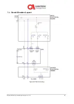
Using Figure 51 as an example, optimal discrimination of circuit breakers in series can be achieved
by choosing them in such a way that when a short circuit occurs, the response of circuit breaker
feeding the bypass line (CB01) line will be based on thermal (slower-acting) tripping, while the
circuit breaker closest to the short circuit (CB05) will respond based on magnetic (instantaneous)
tripping. In most cases we would want the intermediate circuit breaker (CB03) to respond
thermally to a short in Load 2, but with a shorter delay than that of CB01.
Refer to Table 4 for maximum input current values and maximum bypass current values, and
recommended circuit breaker ratings.
In order to protect the UPS's bypass contactor and also the main input of the UPS, for all
scenarios including short circuit, Gamatronic recommends the following:
The circuit breaker that feeds the bypass input line and the circuit breaker feeding the main
input of UPS shall have no magnetic protection delay, or a maximum magnetic protection
delay of 50 msec. This ensures that the circuit breaker will interrupt the short circuit before
any damage can be done to the static switch contactor and the power modules.
If you choose to use a time-delay circuit breaker on the bypass input line, it must be
rated to the maximum bypass input current.
When using a circuit breaker with delayed magnetic protection, the ability of the cables and
the rest of the infrastructure to withstand a short circuit must be taken in account.
Where local electrical codes are more stringent than the above
recommendations, local electrical codes take priority.


