UPS for 400 Vac Grid, Installation Guide, doc. rel. 3.0
81
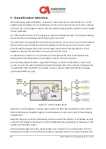
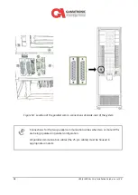
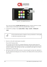
Figure 58: The crown icon indicates the Master UPS
A crown-shaped icon appears on the
System Menu > Status > Modules
screen
of the Master UPS.
8.
Put the slave systems in multisystem mode (
System Menu > Setup > System Type >
Multisystem mode
).
9.
For each slave system, compare the output voltage of each phase to that of the master
system.
Any voltage difference should be no greater than 2 %.
If the difference in output voltage is greater than 2 % for any phase, navigate to the
System
Menu > Status
screen, tap the
Modules
icon, and then tap the
Output
tab at the bottom of
the page.
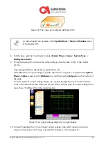
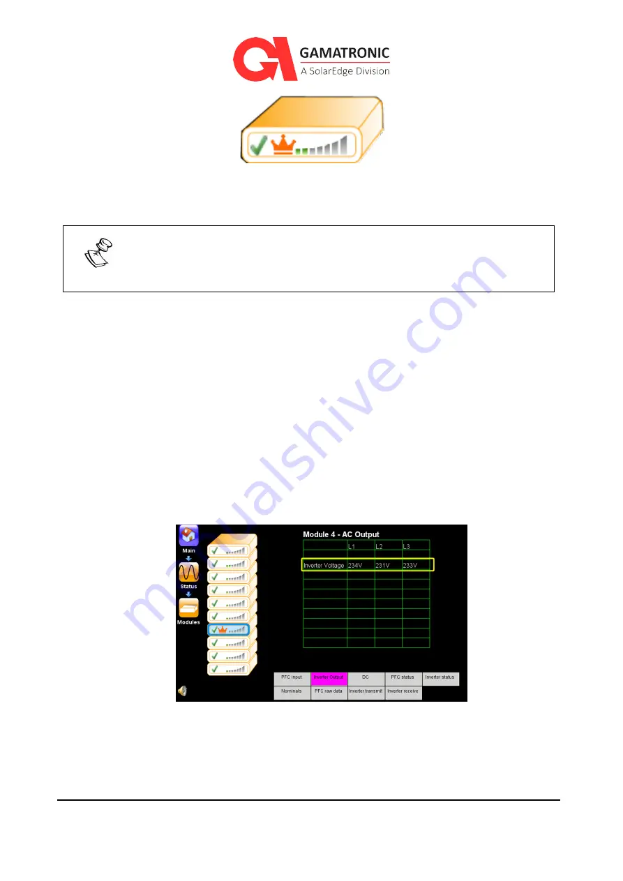
You will see the ac output voltage display, per module. By tapping on each of the module
icons on the left side of the screen you can see which modules have an output voltage that is
more than 2 % different from the master system.
Figure 59: Ac output voltage display for a single module
10.
For each module with an “out of range” output voltage, note which module it is, which
phase or phases are out of range, and what the voltage is. Then, navigate to:

