88
UPS for 400 Vac Grid, Installation Guide, doc. rel. 3.0
7.2.
Transferring the UPS to maintenance Bypass mode from
normal mode
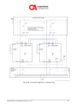
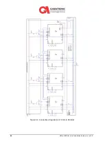
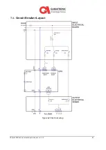
In normal operation, the UPS's ac circuit breakers are positioned as shown in Table 11 (see Figure
62 for CB locations).
Table 11: Normal mode operating position of the circuit breakers
Battery box input
(on battery box)
Rectifier ac input
(CB 2)
Bypass ac input
(CB 3)
UPS AC output
(CB 5)
Maintenance bypass
(CB 6)
ON
ON
ON
ON
OFF
To put the system in maintenance Bypass mode:
1.
Verify with a multimeter on CB6 that there is no voltage difference between the input
and output of each phase.
If there is, there is a bad phase rotation either on the input of the system or on the
maintenance bypass CBs 4 and/or 6. This will have to be corrected before the
system can be put in maintenance bypass. DO NOT CLOSE CB 4 OR 6, THIS WILL
CAUSE A SHORT BETWEEN PHASES.
2.
Verify that all three phases of the bypass input voltages are present and the inverter
and bypass are synchronized on the system controller status screen. (If they are not, the
UPS cannot transfer to Bypass mode.)
3.
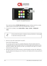
On the system controller LCD screen select
Operations > transfer load to bypass
.
4.
Verify that the load is being supported by the bypass one on the
Status
screen.
Then, operate the UPS's ac circuit breakers as follows:
1.
Switch ON the MAINTENANCE BYPASS circuit breaker.
2.
Switch OFF the AC OUTPUT circuit breaker.
3.
Switch OFF the RECTIFIER AC INPUT circuit breaker.
4.
Switch OFF the BYPASS AC INPUT circuit breaker.
5.
Switch OFF the BATTERY INPUT circuit breaker.

