background image

41

L30US-IB80, L30US-IB00, L40US UPS


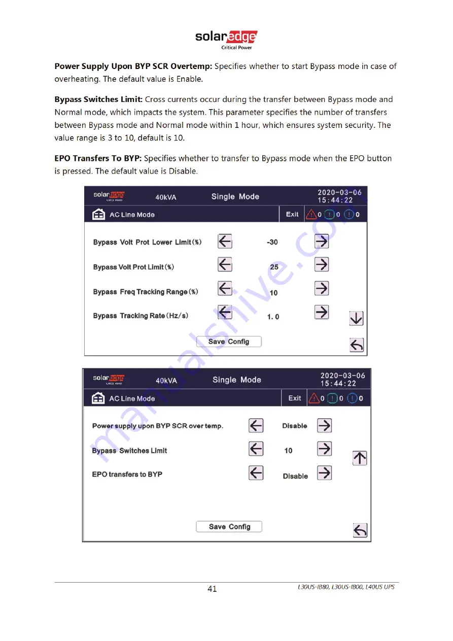
Power Supply Upon BYP SCR Overtemp: 

Specifies whether to start Bypass mode in case of 

overheating. The default value is Enable. 

Bypass Switches Limit: 

Cross currents occur during the transfer between Bypass mode and 

Normal mode, which impacts the system. This parameter specifies the number of transfers 
between Bypass mode and Normal mode within 1 hour, which ensures system security. The 
value range is 3 to 10, default is 10. 

EPO Transfers To BYP: 

Specifies whether to transfer to Bypass mode when the EPO button 

is pressed. The default value is Disable. 


Summary of Contents for L30US-IB00

Page 1: ...Uninterruptable Power Supply for 208VAC Grid L30US IB80 L30US IB00 L40US User Guide Version 2 0 March 2022 Cat No 2MUM...

Page 2: ......

Page 3: ...itten permission of SolarEdge Inc All company and brand products and service names are trademarks or registered trademarks of their respective holders Patent marking notice see http www solaredge com...

Page 4: ...d during installation and maintenance of the UPS and batteries allowing you to correctly set up your system for the maximum safety and performance Included is information on customer support and servi...

Page 5: ...ODES 15 4 1 1 Normal mode 15 4 1 2 Battery mode Stored energy mode 15 4 1 3 Maintenance mode Manual bypass 16 4 1 4 Bypass mode 16 4 1 5 ECO mode 17 4 2 UPS OPERATION 18 4 2 1 Start procedure 18 4 2 2...

Page 6: ...tput setting 46 4 3 7 4 Battery setting 47 4 3 7 5 Dry contact setup 49 4 3 8 Maintenance Touch correction and battery self test 50 4 3 8 1 Battery self check 50 4 3 8 2 Timing daily 51 4 3 8 3 Timing...

Page 7: ...QUIPMENT PAGE 14 FIGURE 9 MUSER5000APPEND EQUIPMENT MANUAL SETTING PAGE 14 FIGURE 10 NORMAL MODE 15 FIGURE 11 BATTERY MODE 16 FIGURE 12 MAINTENANCE MODE MANUAL BYPASS 16 FIGURE 13 BYPASS MODE 17 FIGUR...

Page 8: ...W 9 TABLE 3 DIMENSIONS AND WEIGHTS 11 TABLE 4 COMMUNICATION PANEL 12 TABLE 5 LCD ANDLED DISPLAY 25 TABLE 6 OPERATIONAL STATUS AND MODE S 55 TABLE 7 FAULT INFORMATION 56 TABLE 8 ALARM INFORMATION 58 TA...

Page 9: ...eviations in this document are according to IEEE 280 Standard Letter Symbols for Quantities Used in Electrical Science and Electrical Engineering 1 2 Safety Symbols Information The following safety sy...

Page 10: ...of life Do not proceed beyond a warning note until the indicated conditions are fully understood and met 1 3 Technical Support You can contact technical support via any of the following methods SOLAR...

Page 11: ...ly even when the input AC power is disconnected CAUTION No user serviceable parts Risk of electrical shock do not remove cover No user serviceable parts inside Refer servicing to qualified service per...

Page 12: ...ies located in a service access area 1 Servicing of batteries should be performed or supervised by personnel knowledgeable about batteries and the required precautions 2 Risk of explosion if battery i...

Page 13: ...hould be taken to install the UPS in an indoor environment which is under temperature and humidity control free from electrically conductive particles with reduced risk of electric shock It is best to...

Page 14: ...blem might occur Digital Control This series UPS is controlled by its Digital Signal Processor DSP providing increased reliability optimized performance self protection self diagnostics and many more...

Page 15: ...device and external or internal batteries make up the system Depending on the site and load requirements of the specific installation certain additional options are available for the solution Plannin...

Page 16: ...8 L30US IB80 L30US IB00 L40US UPS 3 4 Cabinet view Figure 1 Front view Side view of L30US IB80 L30US IB00 and L40US Figure 2 Front view without door and Rear View of L30US IB80 and L30US IB00...

Page 17: ...t door and Rear View of L40US Table 2 Cabinet overview 1 LCD panel 2 Front door and lock 3 Mains input breaker 4 Bypass input breaker 5 Maintenance breaker cover 6 Maintenance breaker 7 Output breaker...

Page 18: ...10 L30US IB80 L30US IB00 L40US UPS 3 5 Dimensions and Weight Figure 4 Dimensions...

Page 19: ...S Table 3 Dimensions and Weights Model Width Depth Height Weight L30US IB80 400mm 15 75 935mm 36 8 1065mm 41 9 374kg 825lb L30US IB00 400mm 15 75 935mm 36 8 1065mm 41 9 162kg 357lb L40US 400mm 15 75 9...

Page 20: ...or backfeed protection 120VDC 150mA 6 BAT_SW detects battery switch status normally open 12VDC 15mA 7 RS232 port 8 USB port 9 RS485 port for temperature sensor 10 Battery temperature sensor NTC 11 Col...

Page 21: ...eter Setting choose COM according to your UPS choose 9600 for baud rate choose modbus for protocol then click Save setting Figure 7 Muser5000 communication setting page 4 On the main page of Muser5000...

Page 22: ...l the UPS ID address in the Equipment address field Figure 9 Muser5000 Append equipment manual setting page 6 Click the Append button Connection between the UPS and the computer is now established CAU...

Page 23: ...and boosting charging the battery simultaneously Then the inverter converts DC power to AC and supplies it to the load SINGLE INPUT Mains Input DUAL INPUT Mains Input and Bypass Input Figure 10 Normal...

Page 24: ...intenance mode Manual bypass 4 1 4 Bypass mode In case the inverter is out of order or overload occurs the static bypass will be activated to transfer the load from the inverter supply to bypass suppl...

Page 25: ...to the load is not critical the UPS can be set in ECO mode to increase the efficiency of the power supplied In ECO mode the UPS works in Line interactive mode that is on bypass supply When the AC is o...

Page 26: ...rectifier fails at startup the fault LED will turn on When the inverter starts up the UPS will transfer to inverter mode then the inverter LED will light up 5 Make sure that the batteries parameters m...

Page 27: ...e and the power is not conditioned 4 2 4 Switch to mechanical bypass CAUTION In case the UPS is running normally and can be controlled through the display carry out steps 1 to 6 otherwise jump to Step...

Page 28: ...e switch cover The rectifier will operate normally after 30 seconds If the inverter works normally the system will be transferred from bypass mode to normal mode 4 2 6 Cold start procedure CAUTION Fol...

Page 29: ...eakers are opened there will be no output 1 For L30US IB80 L30US IB00 shut down the inverter navigate to common inv on off single off see 4 3 9 1 2 For L40US turn OFF the BATTERY breaker 3 Turn OFF th...

Page 30: ...bar capacitors to be completely discharged 4 2 8 Parallel setting Connect the UPS to the computer See 3 6 Power on the UPS Open Muser5000 software after connecting to the UPS successfully click Syste...

Page 31: ...e value then click Set see the figure below If the UPS sounds a beep that means the setting is correct Figure 18 Muser5000 work mode setting page At the screen of Data Set click Ups ID write a value f...

Page 32: ...the equipment might be interrupted If it happens reconnect in accordance with the instructions above CAUTION Parallel cable cannot be connected when setting the parallel parameters After setting the...

Page 33: ...0 L30US IB00 L40US UPS 4 3 LCD control panel 4 3 1 Overview Figure 20 LCD control panel introduction Table 5 LCD and LED display 1 Fault LED 2 Bypass mode LED 3 Battery mode LED 4 Inverter work LED 5...

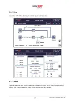
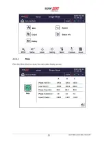
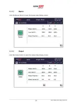
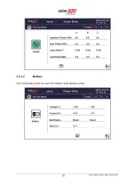
Page 34: ...ions than described in this manual This chapter describes the UPS GUI its functions and navigation On any screen click return to return to the previous screen click home to return to the main screen C...

Page 35: ......

Page 36: ......

Page 37: ......

Page 38: ......

Page 39: ......

Page 40: ......

Page 41: ......

Page 42: ......

Page 43: ......

Page 44: ......

Page 45: ......

Page 46: ......

Page 47: ......

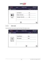
Page 48: ...threshold for the bypass voltage the system determines that the bypass voltage is abnormal and that the bypass is unavailable NOTE When the voltage level is 120V the value range is 10 15 20 25 and 20...

Page 49: ...rrents occur during the transfer between Bypass mode and Normal mode which impacts the system This parameter specifies the number of transfers between Bypass mode and Normal mode within 1 hour which e...

Page 50: ...B00 L40US UPS 4 3 7 Advanced settings Click advanced setting input the correct password The user password is 499283 NOTE This operation is recommended to be operated by professionals or under the guid...

Page 51: ......

Page 52: ......

Page 53: ...parallel system Cabinet Parallel Basic Units Parallel cabinet number must modify the total parallel cabinet number after setting work mode to parallel mode The value can only be 2 because only two UPS...

Page 54: ......

Page 55: ......

Page 56: ......

Page 57: ...e Bypass Feedback Trip Enable or disable bypass feedback output The default value is Disable External Maint Breaker MT Enable or disable external maintenance breaker connection detection The default v...

Page 58: ......

Page 59: ...51 L30US IB80 L30US IB00 L40US UPS 4 3 8 2 Timing daily Modify the check date and time 10S default 10min EOD 4 3 8 3 Timing weekly Modify the check date and time 10S default 10min EOD...

Page 60: ......

Page 61: ......

Page 62: ......

Page 63: ...e No Blink 0 5s Blink 0 5s Blink 0 5s Blink 0 5s UPS Online Mode Normal NO Beeps NO Beeps Off Off Off On UPS Battery Mode Beeps 2s Yes Off Off On Off UPS Battery test Mode NO Beeps NO Beeps Off Off On...

Page 64: ...ps continuously Fault LED lit 7 00C Charge SCR Fault Beeps continuously Fault LED lit 8 00E Fan Fault Beeps continuously Fault LED lit 9 011 Fan Power fault Beeps continuously Fault LED lit 10 012 Cha...

Page 65: ...s Fault LED lit 28 061 DC bus abnormal Beeps continuously Fault LED lit 29 064 INV DSP Power Fault Beeps continuously Fault LED lit 30 067 INV Over Temperature Twice per second Fault LED lit 31 068 Lo...

Page 66: ...king 2 104 BAT Low Pre warning Once per second BATTERY LED blinking 3 105 Battery Reverse Twice per second BATTERY LED blinking 4 106 Battery EOD Once per second BATTERY LED blinking 5 107 Battery Vol...

Page 67: ...142 Unit quantity mismatch Once per 2 seconds FAULT LED blinking 21 143 Parallel Overload Once per 2 seconds INVERTER LED blinking 22 144 Bypass Overload Once per 2 seconds BYPASS LED blinking 23 145...

Page 68: ...Supports multiple operating systems Windows Mac Linux UPS can be monitored remotely through the network Can communicate through web based user interface Supports e mail alarm Supports Multi user permi...

Page 69: ...PS Alarm and UPS Shutdown The relay communication card contains six dry contact outputs and one dry input The inputs and outputs are factory programmed according to functions listed in the Table Figur...

Page 70: ...62 L30US IB80 L30US IB00 L40US UPS 6 Inverter On 7 Summary Alarm 8 Common 9 Remote Shutdown Input 5 12V Figure 23 Relay overview...

Page 71: ...echnical rating 30KW power module x1 20KW power module x2 Efficiency with linear load Normal mode Up to 94 ECO mode Up to 98 Short circuit capacity Icc KAIC 5 Parallel system integrated parallel Stati...

Page 72: ...flexibility Optional Voltage 96 108 120 132 144 156VDC 16 18 20 22 24 26PCS OPTIONAL 192VDC 312VDC 16 26pcs 20 pcs define 20 26pcs no power derating 18pcs output power factor 0 9 16pcs output power fa...

Page 73: ...up Frequency 10 5 4 2 1 Upper limit 10 15 20 or 25 default 20 Lower limit 10 20 30 or 40 default 30 Output voltage compensation support downstream transformer 5 5 Output rate current 83A 111A System f...

Page 74: ...y contact port Output EPO Yes remote EPO Language 8 main languages English French Simplified Chinese Spanish German Russian Italian Brazilian Portuguese Environmental Environment Operating Temperature...

Page 75: ...r side DC Battery Rear side Protection degree Standard IP IP20 PCB Conformal coating Installation Wheels and leveling feet Net weight See Table 3 Standards Approving Agency TUV RHEINLAND CHINA CCIC Ag...

Page 76: ...Measure if the UPS input voltage frequency is within the window Check if UPS input is switched on 2 Utility is normal but Utility LED does not light up and the UPS operates in battery mode The input b...

Page 77: ...ir the short circuit and then restart the UPS 8 The UPS only works in bypass mode The UPS is set to ECO mode Set the UPS working mode to Normal mode 9 Cannot Black start 1 Battery switch is not proper...

Page 78: ...4256 7784 C...
Reviews: